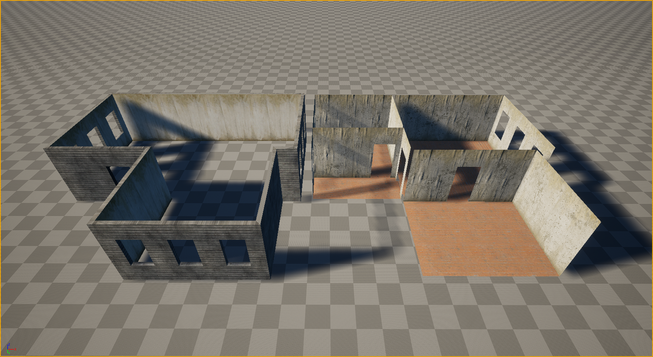
Visualizing the 'Shell & Box' approach. On the left: the merged exterior shell. On the right: the single-sided interior room box


 Tom_Axler


 working on this vehicle (Mobile Exploration Complex) for the past few months. Finishing up detailing stage, going to move on to textures and then rigging soon. Inspired by Soviet tech, Cyberpunk and Star Citizen. Really enjoying the process and learning that comes with it.
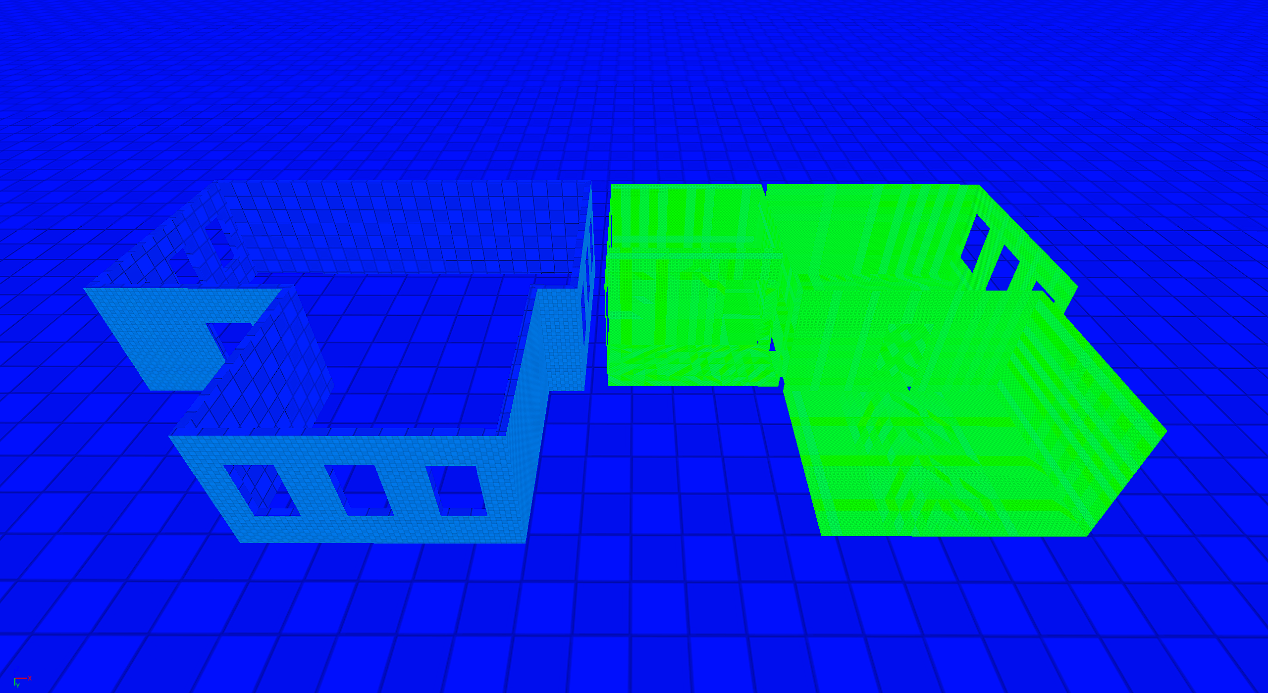
 Frozishe

 Eric Chadwick
 Working on a sci fi environment - Blender & Unreal. Blockout/Design Stage
 Peyd3d
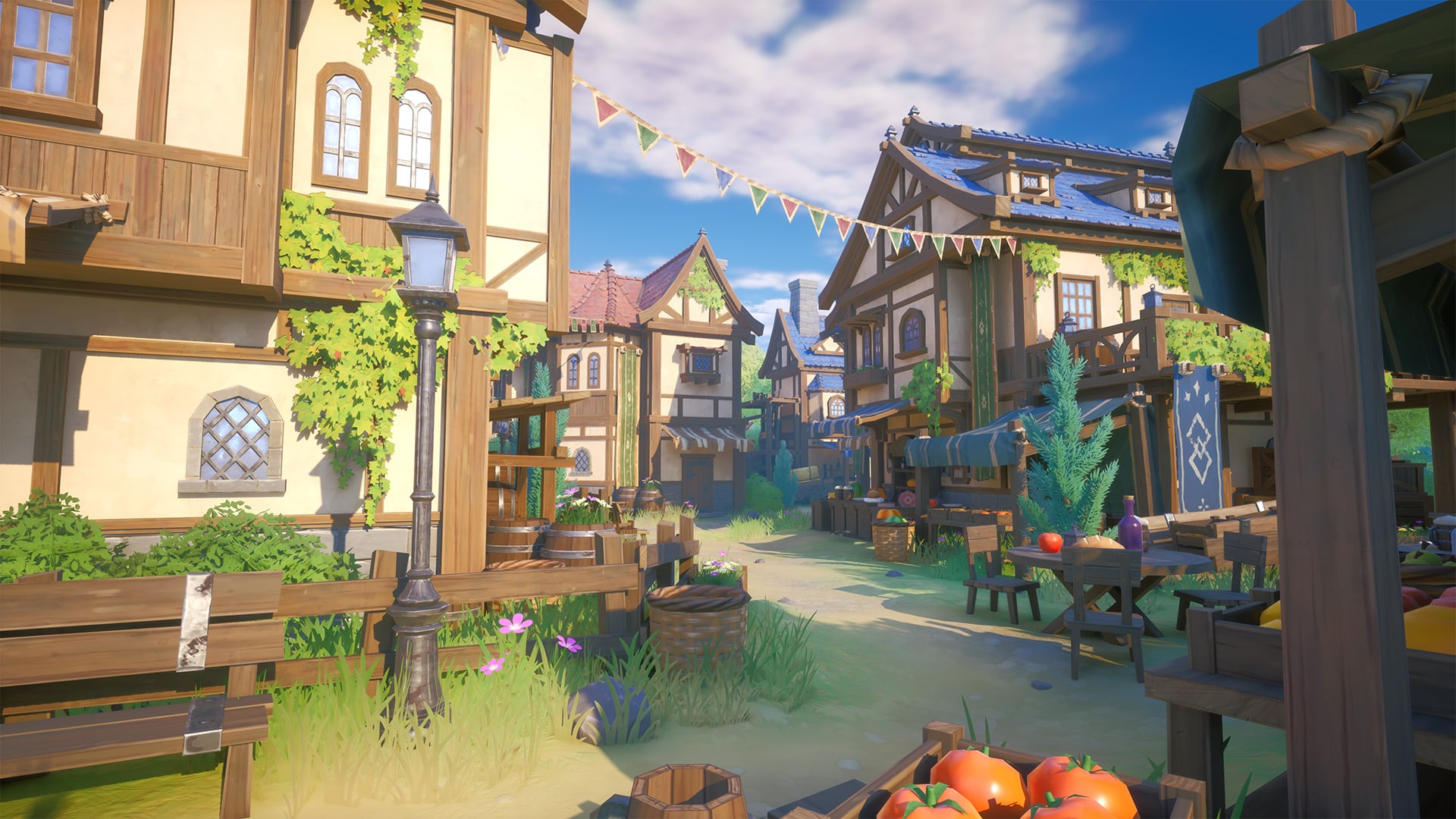
Hi everyone,
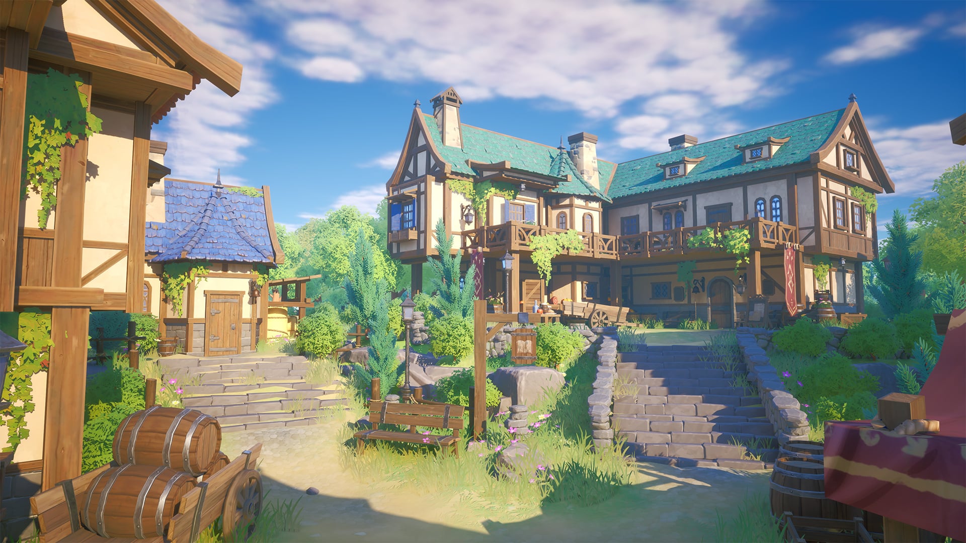
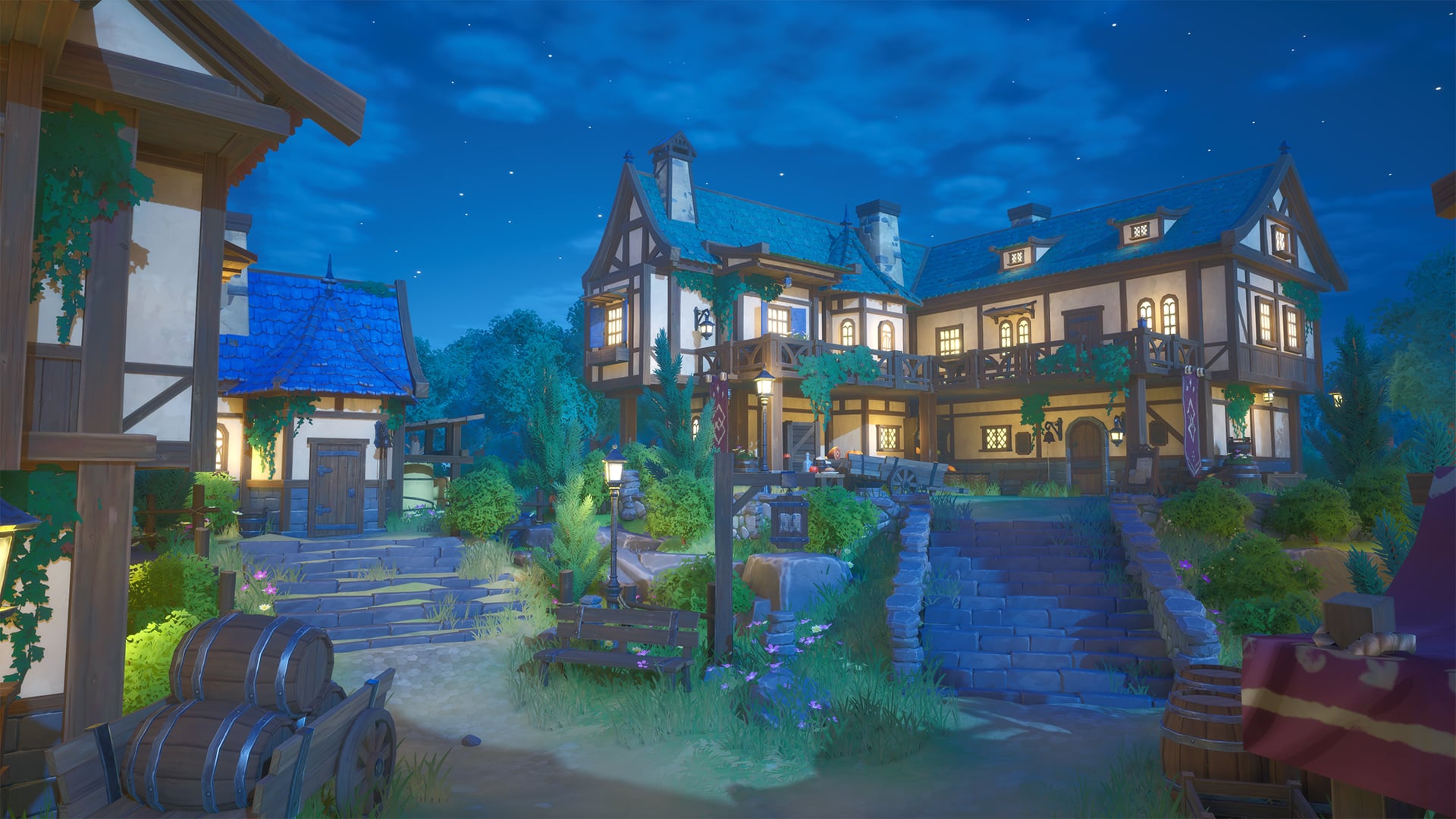
Just wanted to share a project I've been working on—a stylized, modular medieval city built for Unreal Engine 5.
My main goal was to achieve a vibrant, anime/Ghibli-inspired aesthetic while keeping everything extremely optimized for real-time performance. Everything is modular, from the structural pieces to the props, allowing for quick town layouts.
Technical Specs:
Workflow: Low-poly geometry with hand-painted style textures.
Engine: UE 5 (Lumen & Nanite supported).
Optimization: Setup with RVT blending for foliage and optimized master materials for easy color tinting.


 Seivo
Seivo


 Azlios