As much as I agree that this isn't the most productive thread, I also think there is definitely something to be said about how the most recent realistic character/facial tech is seemingly messing things up in a weird, hard to describe way.
Of course the average gamer and game journalist doesn't have the background to pinpoint it, but these facial animation systems just seem to have a tendency to make things slide towards a weird uncanny look. And it just so happens to be especially noticeable on female characters attempting to be realistic but without closely matching a real life actress.
I am replaying Revengence at the moment and I am amazed by some of the visuals. The rendering engine is of course way outdated, but it is fast and butery smooth. And the facial animation on some characters is really damn cool, even showing some nice anticipation on the phonemes which to me illustrates an art team in absolute control of their craft, even with lower ressources from 2013. And something as simple as covering one of the eyes of the characters or keeping them in shadows seems to make the viewer "fill in the blanks".
Of course calling a game woke for featuring yet another sassy girlboss lead isn't the most elegant way to express it, but game studios and the american media and cultural landscape in general are 100% responsible for that anyways after years of advocating for sexist "representation" and expressing overtly racist positions - not gamers. I feel like under the surface gamers might be simply expressing that they just want more cool "game-games" as opposed to yet another attempt at retro 80s nostalgia.
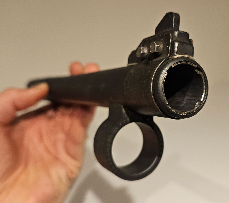
Also I find it hilarious that the team at ND didn't even take the time to look at a real person buzzing their head. This female bounty hunter protagonist is holding the trimmer the wrong way around
I think Michael was echoing Alex_J's sentiment, that you tend to type long posts which do not seem to make a coherent point.
Besides being long-winded, you seem to focus on social media controversies that are not created nor debated by actual game developers.
So for most Polycount members it's really just a lot of hot air.
I don't like singling out any one person, so I try to stay out of the conversation. I think you're honest in your efforts to gather more information that can impact design choices for 3D character models. However you seem to be doing so in a vacuum, without understanding how design decisions are actually made, in actual game development production.
Again, some time passed since last update. The longer I wait with updates, the more likely it is I miss stuff or don't post at all because then it's too much work scraping together the images I shall try to post more often, less mixed content maybe - will make it more structured too.
Anyways, what has happened since last post?
Found a new freelance project after a drought period which made me question myself. I'm currently in my second year working as a freelancer. Compared to when I was employed, I feel more pressure. When I have a project, it's often quite intense, when I don't, I'm worried that I won't find the next one Diversity of tasks/challenges is great :-B I suppose when it gets too much of a struggle, I'll have to look for employment again.
Some side quests I made some progress on:
Started collaborating with AlexJ on assets, see his 3d action game development thread. Working that way feels fun and refreshing. I like tweaking existing models.
Hoplite an early test I did
a recent version
Satyrs Modified base mesh created by Alex
Lamassu
Anzu - picked up mesh from Alex
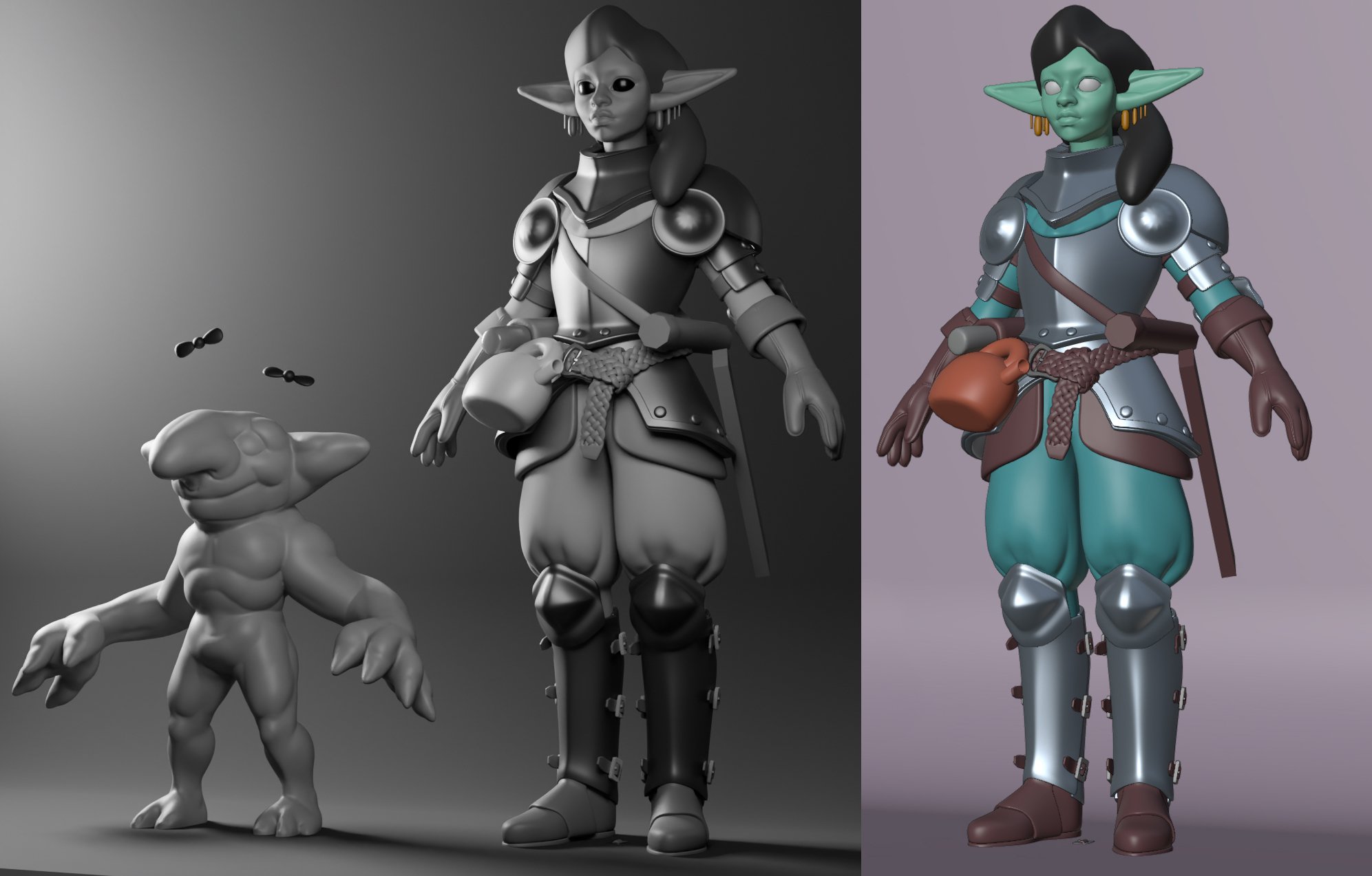
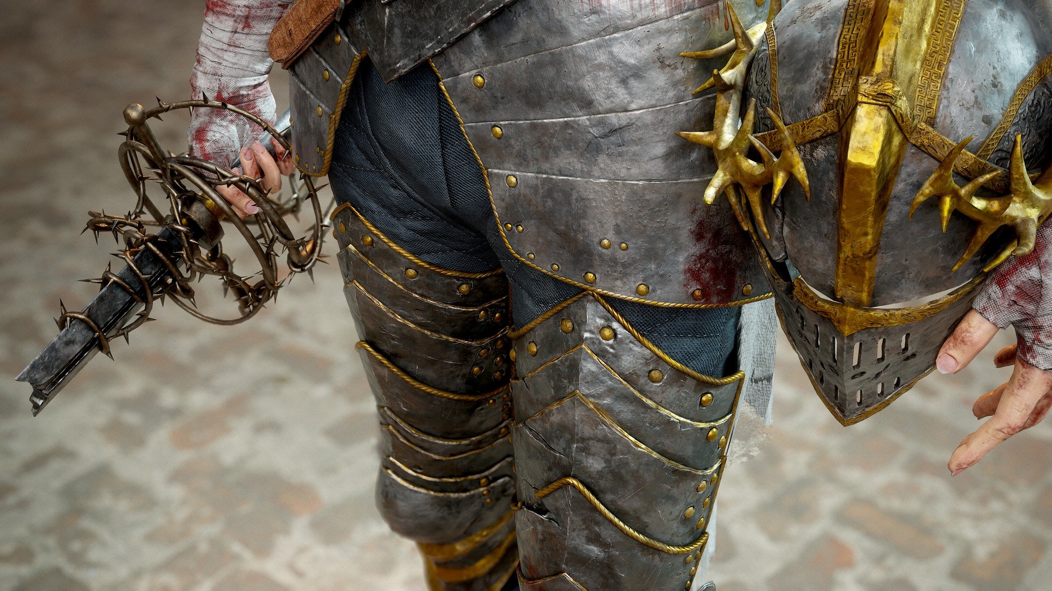
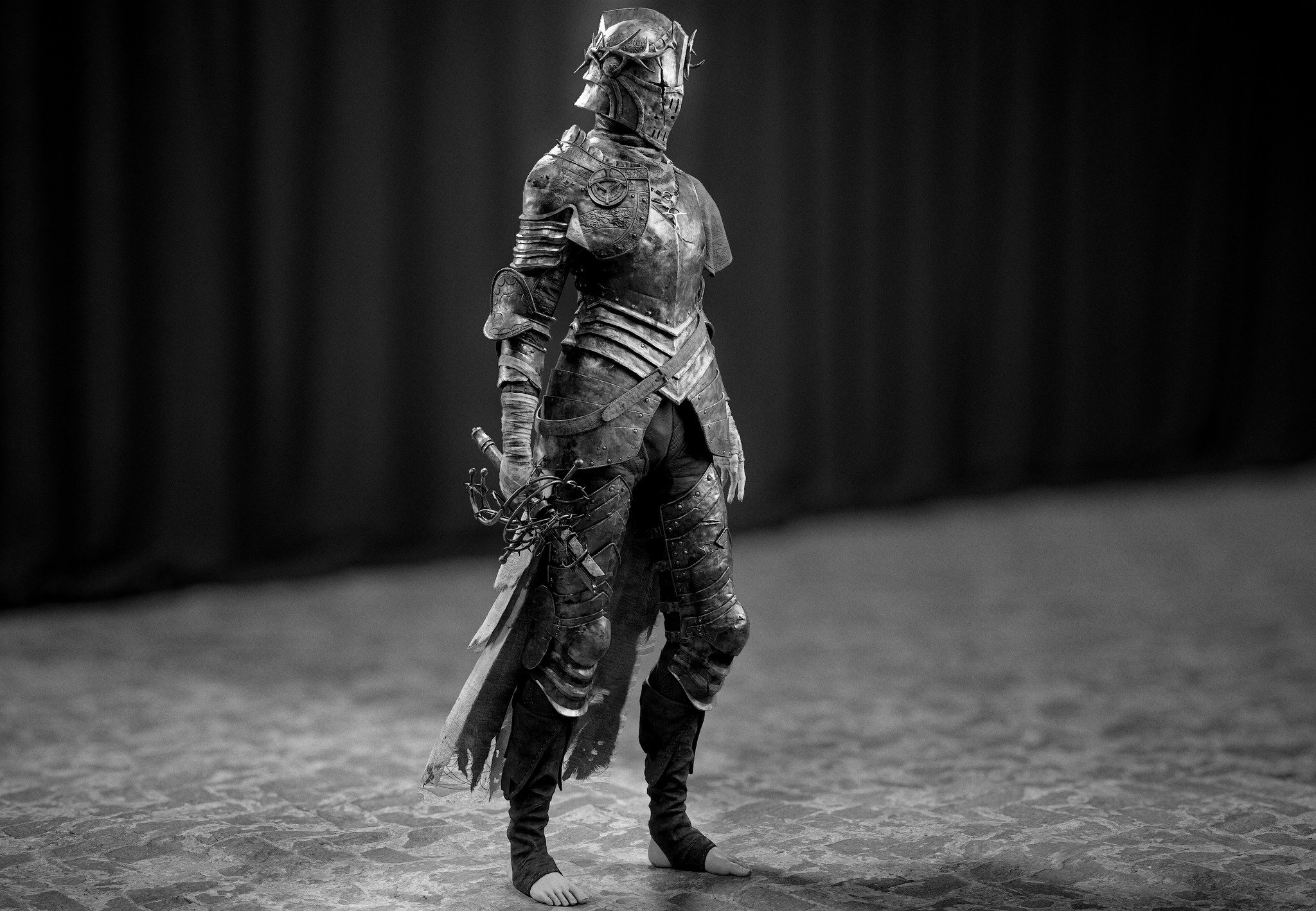
Character for a Squad mod. This is maybe the third iteration I'm doing. Get it together!
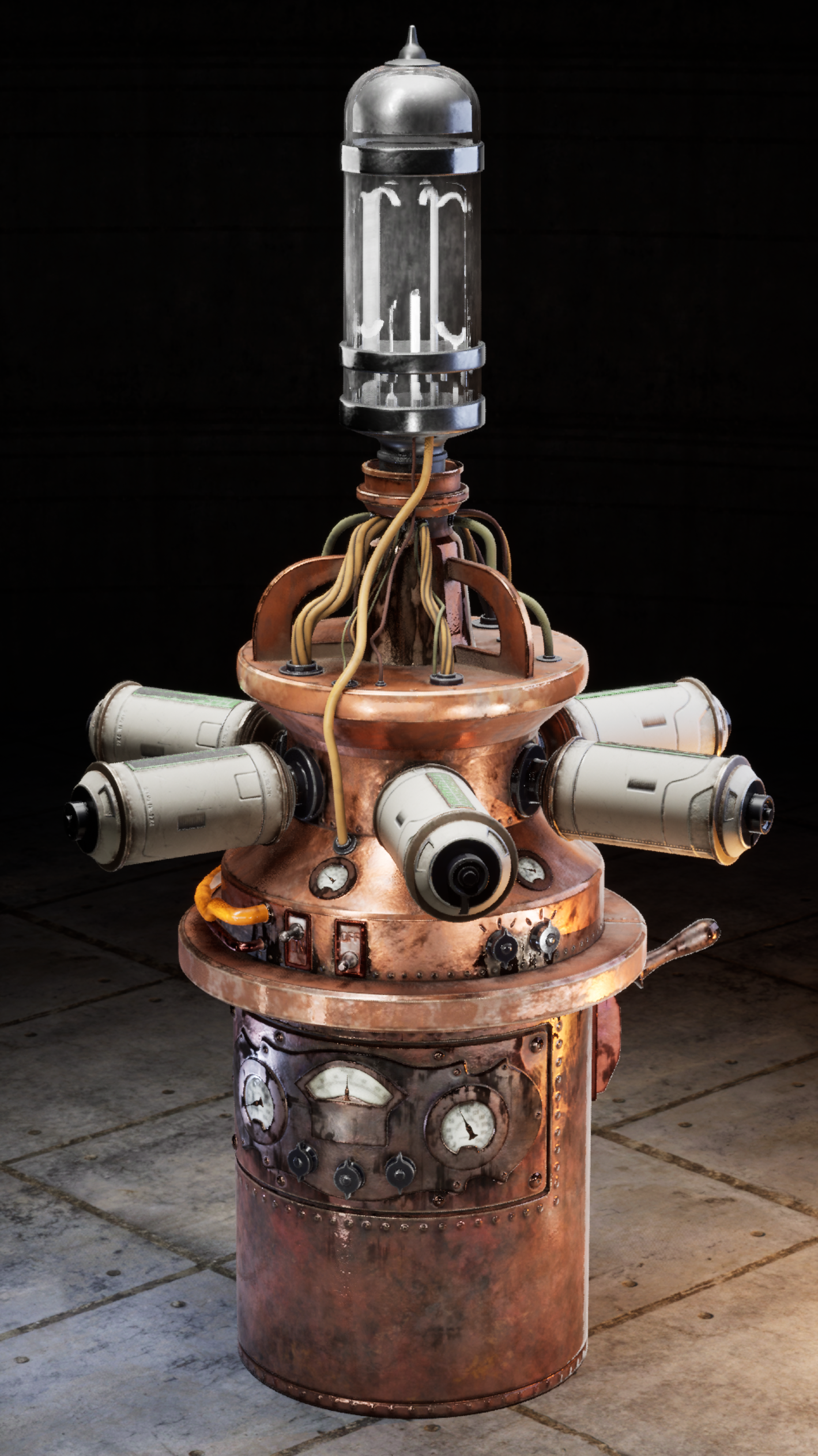
Revisited "Got Mail?" project, an old environment challenge entry. Tweaked assets some more, imported into Unreal, build a small scene, did renders and a short clip.
Further improvements: - Add more breakup/detail to large shapes (decals?) - fill empty space (back, right), maybe a bicycle leaned against the back, a small shed, ... - move ivy closer to wall - improve trim sheet - particles in air? Visualization of wind. - character for scale? Simplified shapes.
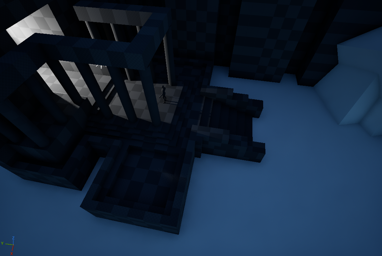
Blocked out a market stand for the current bi-monthly. Will I continue it?
It's been a long time, friends, though we haven't met. But I'd like to share with you a personal project I've been working on lately, Gleanings. This was done independently by myself from concept sketches to modeling and final rendering. It took a total of five days. Because I was recently unemployed and resting at home. I have some time to do my favorite things. This project mainly uses 3d max to make the general shape, zbrush to sculpt the details, texture in substance, rendering using Marmoset. Welcome to learn and exchange together.https://www.artstation.com/artwork/vDWABD https://www.artstation.com/artwork/vDWABDhttps://www.artstation.com/artwork/vDWABD
Subdivision modeling: mesh complexity and shape accuracy.
Modeling hard surface objects with more organic surface features, like stamped metal parts and castings, can be challenging because of the complex compound curves and the odd combination of hard and soft shape transitions. When working on these types of models it can be helpful to block out the major forms of the complex compound curves with a relatively simple cage mesh then apply the subdivision to lock in the shapes and provide support for smaller surface features.
While this strategy of incrementally applying subdivision to a model with a lot of complex compound curves does tend to work well, one thing to avoid is applying too high of a subdivision level too early in the modeling process. Subdividing a mesh beyond the minimum amount of geometry needed to hold the shapes tends to introduce a lot of unnecessary mesh complexity. Which can make it difficult to adjust the larger shapes without generating slight undulations in the subdivided mesh.
Over subdividing the mesh can also make it difficult to add larger secondary surface features without having to add or reroute support loops. This can be especially problematic when the additional support loops deform the underlying surface or significantly change the segment spacing of a curve on the larger shape. These extra support loops often generate undesired creasing or pinching elsewhere on the curve of the larger form and it can be extremely difficult to manually even out the curvature.
Below is an example of what the modeling process can look like when too much subdivision is applied to the basic shape. Though most of the larger forms on the tank are correct, applying the subdivision too early has made it difficult to adjust the mesh in a way that effectively creates some of the secondary shapes where the sides of the tank curve inwards. This unnecessary mesh complexity also tends to actively discourage fully exploring some of the finer shape transitions and can push artists to try manually carving the details into the larger shape.
While there are some cases where it's necessary to model sharper raised or depressed panel lines (welds, gaps, bead rolls, coining, embossing, etc.) most deep shapes formed in a single sheet of metal have very soft, gradual shape transitions. With traditional metal forming, extremely sharp or harsh shape transitions on pressed metal objects tend to indicate spots where multiple parts have been joined together. Too much harshness in the shape transitions can give the model a different appearance or surface read from the actual object.
When modeling hard surface objects with soft compound curves it's
important to analyze the reference images and establish realistic
transitions between the primary and secondary surface forms. Gather good reference images that show the object from multiple angles and under different lighting conditions then study how the shapes flow into each other.
Below is an example of what the modelling process can look like when less geometry is used and the mesh topology is kept relatively clean and simple. Start by blocking out the major forms and only apply the subdivision when it's absolutely necessary to support the shapes. Keeping things as simple as possible for as
long as possible tends to make larger shapes easier to work with.
Try
working in some of the secondary shapes earlier in the block out
process and carry that simplicity over into the base mesh. This should help
reduce the overall complexity of the cage mesh. It can also be helpful
to deform some of the edge loops on the base mesh so the underlying
topology will fit around the shapes in the references. This will make it
easier to add surface details without having to use a lot of complex
boolean operations.
The closer the shapes are to what's in the references, at the lowest possible subdivision level, the easier it should be to add additional details to the curved surfaces later in the process. Spend the time refining the shape of
the curves at the lowest level that makes sense then work up from there
while keeping things as simple as possible.
Avoid the assumption that a dense or complex mesh is an accurate mesh. Mesh density does tend to increase the quality of a subdivided surface but the position and form the underlying geometry is what really determines the overall accuracy of the mesh. Poorly constructed shapes that don't match the reference images or are inconsistent won't be improved by increasing the mesh density.
In fact there's a lot of situations where arbitrarily increasing the mesh density can actually introduce more issues than it solves. Representing
as much of the surface shapes as possible at the lower levels will also
help keep things relatively simple. When to add additional subdivision
levels or support loops will depend entirely on the complexity of the
shapes / details that need to be added, as well as where it all falls in
the overall modeling process.
Recap:
Take the time to gather quality reference images. Study these reference
images and if necessary draw over them to highlight important shapes and
shape transitions. Carry the block out process as far as it needs to go
to accurately develop all of the shapes. Avoid over subdividing the
mesh and trying to manually carve or batter surface features into shape.
Start with a relatively simple mesh and use the appropriate amount of
geometry to hold the shapes. Let the subdivision do the work of filling
in the geometry and smoothing the shapes.
Subdivision modeling: process optimization, order of operations and flat surface topology.
Process optimization is an important part of skill building and taking
the time to evaluate the underlying assumptions that drive your modeling
strategy can help improve both the efficiency and quality of your modeling process.
Below is a visual overview of a simple modeling task. Fill the cap between two cylinders that have different segment counts and add support loops to create a subdivision ready cage mesh. How much time and effort it takes to complete this simple task will depend on the modeling tools and strategies used.
The following example is a modeling process that's driven by a lot of common preconceptions and assumptions. Here's a breakdown of the rational behind this process and a summary of how the model was created.
Subdivision modeling implies that the cage mesh needs to be all quads with even grid topology to avoid smoothing artifacts. Starting with fixed topology suggest that everything needs to be manually joined together to create the perfect edge flow. Edge extrusion modeling extends the existing topology so it will be the fastest way to fill in the cap. Loop cut, fill and connect are basic operations that provide granular control of the topology layout phase of the process.
Modeling process 1 (≈ 48-62 individual operations.)
Extrude upper outer diameter support loop.
Extrude upper inner diameter support loop.
Fill radial segment - 12x.
Cut lower outer diameter support loop.
Cut low inner diameter support loop.
Join inner diameter support loops as quads - 42x. (Alternate: select and fill as quads - 30x.)
This modeling process relies heavily on a brutally straightforward approach that uses a very limited selection of modeling tools and a strategy that follows whatever trajectory feels right in the moment. There's a significant amount of time spent on repetitive modeling tasks
and the misconception that everything MUST resolve into quads to be
subdivision ready only compounds this problem. What follows is a look at whether or not the previous assumptions created artificial limitations that generated unnecessary complexity.
Modeling process 1 technical parameters:
All quad geometry - Unless there's a specific technical limitation that absolutely requires the cage mesh be all quad geometry there's generally minimal benefit to manually adjusting the topology to create it. Simply subdividing the cage mesh will make it all quads. If quad grid topology is required for other process (like detail sculpting) then using automatic quad re-meshing tools is a better approach. The assumption that all subdivision cage meshes need to be quad grids is something of a misconception and in this case it's an artificial limitation.
Fixed segment counts - Part of the block out process is figuring out how much geometry will be needed for subsequent modeling operations. There will be situations where it's either impossible or impractical to plan for all additional details and in these situations the base geometry will become a limiting factor. This is a realistic technical limitation and it's important to build an understanding of how to work around issues caused by having a limited amount of geometry to work with.
Manual topology routing - There are certain cases where manual topology routing is necessary but unless the automatic tools have failed to create usable topology there's no real benefit to manually creating all of the topology flow. Sometimes there's a tendency to assume that creating every face and placing every support loop by hand improves the quality of the mesh but reality is this is just needless busy work and this behavior should be avoided whenever possible.
Edge extrusion modeling - Basic manual modeling tools can be used to accomplish a wide variety of tasks and tend to have a high degree of granular movement control but that doesn't mean they are always the best tools for the job. The biggest drawback to using these tools is it can be difficult and time consuming to maintain consistent edge width. More complex tools can be used to place support geometry and automatically maintain a consistent edge width. This will improve both the process efficiency and visual quality of the model. Improving the edge width consistency tends to improve the readability of the shapes and helps provide a clean, professional look.
With the exception of fixed segment counts, most of these assumptions introduced artificial limitations that negatively influenced the modeling process by narrowing the tool selection and increasing the number of manual operations. If edge extrusion was the method of choice then it would be much better to extrude the inside and outside segments to form the support loops then fill the faces between them.
The only really important part of the topology is the support loops on either side of the outer bounds of the main shapes. Flat areas are largely unaffected by changes in topology so it makes more sense to average out the the differences between the segments there rather than in the support loop around a key shape transition. With this broader context that's now backed up with experience gained through experimentation it becomes more obvious that the only real constraint here is the starting geometry. The rest of the process is open to interpretation.
The following example is a modeling process that applies what was learned by removing unnecessary limitations, expanding the tool selection and adjusting the order of operations. Here's a breakdown of the rational behind this process and a summary of how the model was created.
Modeling process 2 technical parameters:
Fixed segment counts - In certain situations the underlying topology will be a limiting factor that determines how much geometry is available to work with. In these cases the fixed segment count of the inner and outer diameter is the only true limitations here.
Abandoning the previously mentioned preconceptions means it's possible to explore new ways of approaching the problem of connecting two support loops with different segment counts. Thinking about what's actually important and what tools are available will help identify more efficient ways of adding the support loops around the shapes.
Modeling process 2 (≈ 3-5 individual operations.)
Fill half cap - 2x.
Bevel / chamfer outer and inner diameter to add support loops.
Add edge between inner and outer support loops on the cap - 2x.
Changing the order of operations and tools used means it's possible to add most of the support geometry in a single step and all of the newly added support loops will have a consistent width. The flat area between the two support loops around the inside of the cap is used to absorb any major topology changes without causing any major smoothing artifacts. Not only does this modeling process ensure that potential shading issues are minimized but there's also the added benefit of having a simplified mesh that's easier to work with.
In most cases: the important topology layouts are around the shape boundaries and are made up of the support loops that hold the shapes. Whatever happens on the flat surfaces is often irrelevant. Trying to resolve all of the intersecting edge loops into quad geometry doesn't improve the smoothing results and (in this case) would only add unnecessary complexity.
That's not to say that it's unimportant to be aware of how the underlying topology effects subdivision smoothing behavior or to just ignore technical specifications when situations call of quad grid topology. Instead the message is that, in most cases, a few triangles here and there is a moot point if they aren't causing any major subdivision smoothing artifacts. Along similar lines: N-gons can be especially useful since they make the mesh easier to work with and when used correctly they have virtually no downsides compared to mixed quad / triangle topology.
The most important takeaway here is the most important geometry is the edges that define the shapes and the support loops that back up these shapes.
Below is a sample of a variety of topology strategies that all produce
similar results. Double looping isn't always necessary but it can be
helpful on large flat surfaces where the distance between support loops
is quite wide. It's also worth noting that there's practically no
distinguishable difference between the all quad geometry and the mixed
triangle topology when it's used on a flat surface. This isn't an exhaustive list of all the possible topology combinations but it illustrates the point.
Recap:
Taking time to evaluate the assumptions that drive the modeling process is an important part of skill building. Automatically following popular modeling mantras (without evaluating the broader context behind the how, when and why) can introduce unnecessary process restrictions that tend to lead to extra work and excessive complexity.
Evaluate whether or not these assumptions introduce artificial limitations and experiment with different tools and order of operations to identify simpler and more efficient ways to model the underlying shapes.