many of us on this forum have shown this before. Please take your time and go back, i showed this method on the page before and Perna, Earthquake, Eric and so many more has shown fixes for this. The key to working with curved objects is to have a the edgeflow stay as consist as possible. If you add 2 edges to close to eachother on a curved surface, you'll get bulges, hard surfaces, pinches etc. Try to have them evenely spread. Now, this is just one method of many. This is a old Example that i did. But the principal is there. me a couple of days ago @perna a couple of years ago..
Thx man for help me. i tried this but don't fix yet I will search more information in others thread's
How many segments do you have on your cylinder? Just for the sake of it, how does it turn out when you use a 32 sided cylinder vs a 48 sided? Do you get better visuals? Less is not always better and More is definatly not better, but Enough is good. You're cylinder, needs to be able to hold up The Extruded edges!
42 segments, maybe i can try with 48 or more
No need for that tbh. Now you've picked let's say 40 segments. so the 40 segments means. 1. You have 40 lines (edges) going around in a curve. 2. i want you inbetween one of those edges, cut in /add another Segment, doing so, you already have "support loops" from your original cylinder. Following along? 3. Check the picture, i explain like a proofy.. not! but still. This is overkill, but i just want to you to understand the benefiets of having a mesh "dense" enough to support the cuts you make into it. So you do not have to add 100 extra edges to support once turbosmoothing. I want to clarify, that this is mostly for Curved objects, because on a flat plane, you can have ngons, tris and whatevers and it'll not be seen. If it's not going to deform in an animation.
Man you save my life, thx for yours techniques
Looks good, do these as a excersice every time you start your 3D program to make it As normal as possible
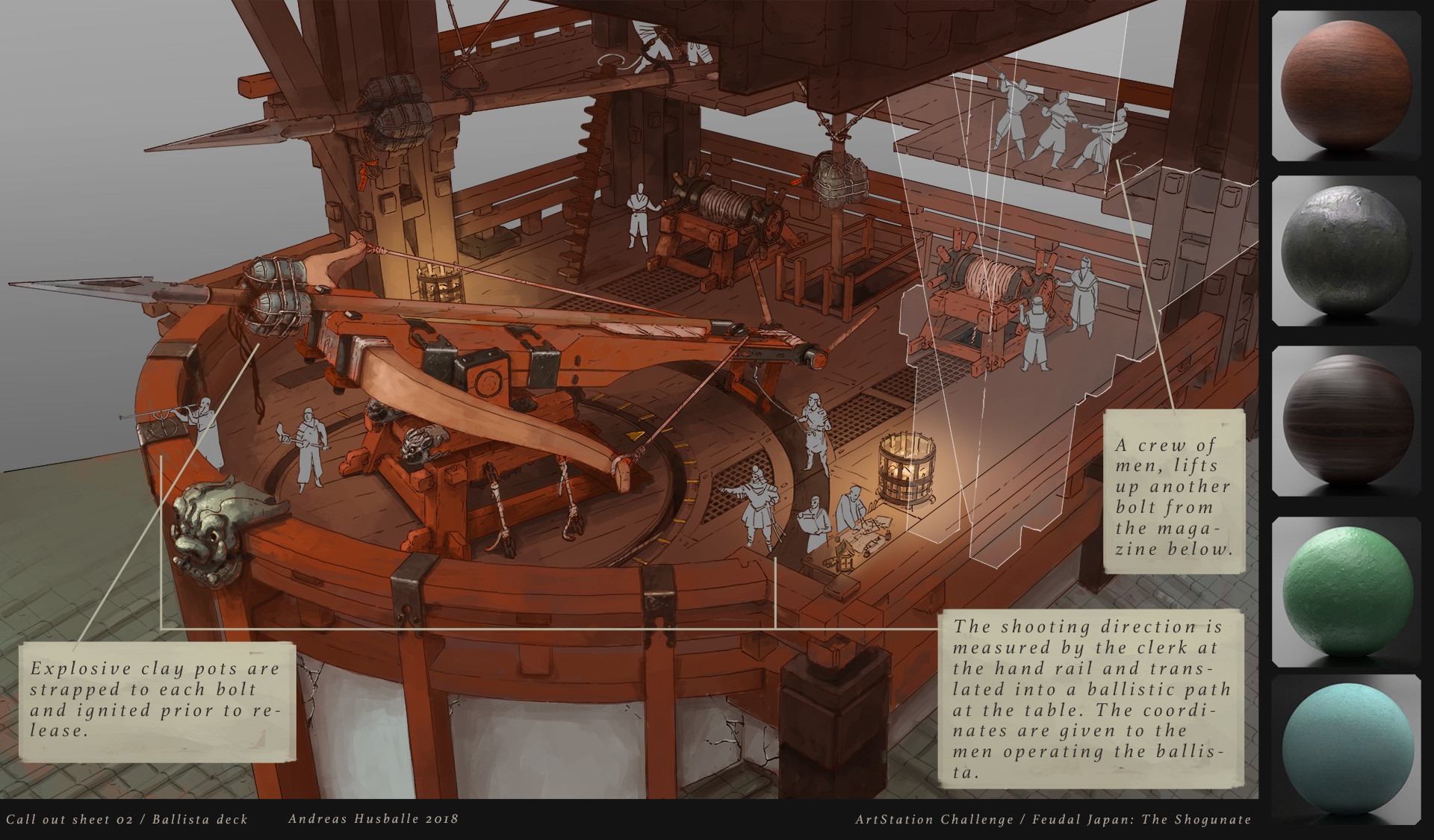
Hey guys, I've been trying to go at making ropes in Maya using curves or Zbrush using IMM Curves but all are tedious and look odd/floaty. Open to any ideas Here are some images:
My attempts -
The concept I am following from Andreas Husballe in the Artstation Challenge -
HI there guys so I tried modeling this in cinema with splines with no success I thought about marvelous designer but I think there must be a better way less time-consuming way.
I need to model the threads on the sofa I attached.
EDIT: these are my failed attempts within cinema4d using 2 bodies on 2 splines one as a rail one as the object on which to clone to. And my cloner is set to blend between the taller and the shorter at the end.ails wi
Hey guys, I've been trying to go at making ropes in Maya using curves or Zbrush using IMM Curves but all are tedious and look odd/floaty. Open to any ideas Here are some images:
My attempts -
The concept I am following from Andreas Husballe in the Artstation Challenge -
The ropes are under tension as displayed in your reference concept image. So try manipulating the curve/s too convey that, also where the bowstring is tied at both ends of the crossbow stave, the knots should be positioned closer to the stave.
Hello. At the moment im working on one project, that based on Unity WebGL, so that meens that all 3d graphics need to be well optimized. And part of my job is to model that lantern (in image). I want to understand how to model these arabic patterns and what i need to use for that? Im thinking that i need to make everythign in geometry and bake it to diffuse map, so it will be in texture. I dont know maybe it will be easier to make those patterns in substance or there other way? Need your advices, guys!
Apologies for the late reply and Happy New Year by the way, hope you have a good one
Anyway, I'd agree plus there's a few other performance considerations to take into account when reading the documentation, so all I can suggest is too prototype/test your work and if needs be further iterate until you've optimised a workable solution, good luck with it.
Can someone advice on how to achieve better edge flow in this piece? Having lost of pinching and i think my corners looks bad.
Cut your intrude/Extrude on faces instead of where the edges are. I've been showing this a couple of time now on the last 3-4 pages.. That even i am making a mistake on this.. This is a fast one with shittier topology and 32 sided mesh. You see a small bulge on the edges but those will be gone when baked and textured. I could've tightened it up but... I'm getting bored on showing the same example
^ Hey no problem, all good and yeah there's a fairly noticeable offset between the two, so one option is to try aligning the 'rail spline' along the top tube of the mesh object?
^ Hey no problem, all good and yeah there's a fairly noticeable offset between the two, so one option is to try aligning the 'rail spline' along the top tube of the mesh object?
Yeah.. no. I this is a result of moving both rails rotating the one or the other sometimes both. I also tried playing with the banking inside the cloner. It just won't work, I even tried with different types of splines ( bezier etc...) Posting here was my last resort.
Is one of these generally acknowledged as 'better' for creating a subdivided section of a circle? To me the one on the right seems to conform slightly more to the correct arc. Does the same rule hold true if the 'ends' of those arcs were extended out straight?
@Rekov the left one should preserve your curve the best, as the length of each segment in the circle is the same. Equal length of- and equal angle between edges = best circle.
I feel like I keep running into the exact same circumstance and never being able to figure it out. It's these 'concave' corners on a curved surface. I cannot for the life of me figure out how to get supporting geometry for a subdivision surface in so that the result appears smooth:
I feel like I keep running into the exact same circumstance and never being able to figure it out. It's these 'concave' corners on a curved surface. I cannot for the life of me figure out how to get supporting geometry for a subdivision surface in so that the result appears smooth:
This has been explained in detail, even on this page at least 3 times.
I feel like I keep running into the exact same circumstance and never being able to figure it out. It's these 'concave' corners on a curved surface. I cannot for the life of me figure out how to get supporting geometry for a subdivision surface in so that the result appears smooth:
But to explain it once again, this is a question of enough supporting and Consistensy in your edgeflow to hold up that shape.. i started of with a simple plane, divided it once in the middle and twice in length. Turbosmoothed 2 times to have enough geo to work with without getting Problems.
Thanks. I think the part that I wasn't getting, and I'm asking just to be sure that I 100% have it now, is that you can't control the edge geometry independently of the level of geometry that the curve itself has. Specifically, edge geometry that isn't perpendicular to the axis of the curve.
So if I wanted to make the corners of this panel tighter, the first step would be increasing the geometry on the curve itself, correct? Or am I wrong about that? I could move the 'vertical' edges without breaking curvature, but I couldn't move the 'horizontal' ones, so I would need to have more segments to the total circle.
What am I missin in the corner here? it pinches when smoothed. I don't want to interrupt the exterior radius so I collapsed the loops and left that angled quad. Coulda sworn that was gonna work!
Thanks. I think the part that I wasn't getting, and I'm asking just to be sure that I 100% have it now, is that you can't control the edge geometry independently of the level of geometry that the curve itself has. Specifically, edge geometry that isn't perpendicular to the axis of the curve.
So if I wanted to make the corners of this panel tighter, the first step would be increasing the geometry on the curve itself, correct? Or am I wrong about that? I could move the 'vertical' edges without breaking curvature, but I couldn't move the 'horizontal' ones, so I would need to have more segments to the total circle.
Problem with panels like this is that the cut is in the center of the quads, otherwise you could just place the corners closer to the support loops. You can try to move the egdes at the corner a bit closer and see if you can live with the bit of shading error. More geo works, though might be overkill in the end, depends on what result you want.
Imho I would not model panels lines like that using subd anymore, if possible I would use bevel or custom normal or even just texture it, depends as well on the result I want.
try moving the edges in like this (i noticed i forgot some edges, but you'll notice which once when you move them, what edge i meant that i forgot)
Solved mine. I just remodeled it with increased radius segments from 48 to 144 and that reduced the tension enough to where any distortion is no longer noticeable.
@prime8 - When I posted my first attempted in here, I was putting the edge of the panel along the edges of the quads, which I thought was why it wasn't working out. I don't know exactly what I was doing wrong there, but it seems to be working a lot better now. And maybe there are better ways of doing panels. I could probably do it in nDO fairly easily, or with bevels, but I would like to be able to do with subdiv at least. And I still think it can produce a slightly better result. I like my meshes to be mathematically precise, and it helps to have an actual model when baking panels that extend across multiple UV islands.
@wirrex - Thanks, that worked perfectly! I don't know why I didn't just try it, except that it seems a little inelegant.
Here are both versions side by side. They both seem decent enough, so I can probably use either situationally. Unless either of you thinks one version is a fundamentally better technique.
Looks good! Try to do it with less geo but with floating geometry
Hello everyone. I'm trying to do some hard-surface modeling, and I'm trying to understand how should I approach these. I already tried modeling them, but had some problems.
This is the box I tried to model. The thing is, its a pain in the ass. I dont know how to approach. I'll explain, first, here's the breakdown of what I understood in Photoshop.
Now, here's the thing. Let's ignore the texture parts. It's easy to do the blockout model. The hardest thing is the panels. As you can see, it stops on a curved surface. I basically cut the model, then bevel it with 3 segments. Then, extrude in. Normally, this should work if the edge loop was "looped" , but it stops abrubtly in the right top corner as you can see in the image. This creates a very annoying triangle that I cant get rid of. One more thing, as you can see, theres also 2 holes on the front piece and one is actually cutting in the panels. If I try to model the circle first then panel, a lot of artifacts occur and I cant find a way to fix the topology.
Also, when you are extruding in, it extrudes in along normals. Some of them extrude in very weirdly. This is actually not the model I tried to do and it has n-gons, but I tried to do this a lot but it didnt work so I did not save any of them, I made this really quick for demonstration. Normally, I fix them up in all quads, though I dont care about how it loops when I do so. Should I? Okay, here's the triangle I'm talking about also the extrusion.
This is the triangle:
This is the extrusion. As you can see, its petruding out for demonstrating purposes, but when you petrude it in, in doesnt go inside normally, it goes the center, like you are scaling it down (??? I actually dont know how to explain this.)
So, here's my 3 questions after this long ass post (sorry :./)
1-Should I not care about SUBD modelling at all and just go full on boolean modeling and beveling on pieces like these? Is this piece possible with SUBD? Because I feel like if I try out boolean modeling, this could work, but is this the right approach? 2-How can I fix this triangle issue on a surface like that? (One of the best things I could think of fixing it was continuing the bevel on it but not extruding in the curved part. It again created weird artifacts.) 3-How can I fix this extrusion problem?
Change your pivot point to median, which will average out alignment for the selected vertex points when inset but IMO I don't think that region of the drawing would have a panel, seems to me more like a design for a decal?!
I'd also suggest persistence if this is a learning exercise, because best practice fundamentals are often learnt through trial and error via cage modelling to begin with, prior too eventually moving onto other techniques.
Yeah, I thought so as well, but I really wanted to do what I initially thought because "what if I need to model something like that in the future?" so I am trying to model it with panels atm.
I honestly didnt know something like this existed. Saw it on tutorials, but didnt think it would work that way. Thanks for the awesome tip, this works quite well in the "circle divots on panels" case. I have one last question, I have some weird normal map bake problems after this, is this because I have geometry on seams? I have a cage, I softened everything selected only the hard edges, marked them as sharp, and I cut my hard edges in UVs. But still things like these happen pretty often in my models. Am I missing something?
This makes a lot of sense, and I'm currently trying to do it this way, but theres a lot of clean-up to do in Zbrush. If there are better ways to do it, please tell me so. I'm still doing it, but cleaning up in Zbrush is very annoying to do
UPDATE: I finally did it! Thanks you two. I will not retopo and texture it, but I finally modeled it with subd and booleans combined. Here's a screenshot:
good job, my only concern is that the white part seems to be painted and not a panel
Hi guys! I'm new to poly-modeling, and most of my theory I got from this exact thread, so I want to say thank you for the awesome advise and the time all of you spend teaching noobs like me and helping each other.
So here's my problem:
I am modeling an old soviet airplane with a cylindrical fuselage (body), and at one point it has an indent, shaped like a smaller cylinder has been pushed in.
Kind of like this
Seems simple, but as soon as I start adding loops to harden the edges, I get all sorts of patterns, but none of them end up looking smooth.
The most obvious way out is to add two horizontal lines to finish the loops like this
But then the roundness of the cylinder is destroyed
I've tried indenting other shapes into a cylinder, but i just can't figure out a pattern that would work, leaving me with pretty 4-sided polygons.
@Mudoxy This topology works almost all of the time for cylindrical shapes, is preferable to maintain the edge loop around the hole somewhat the same to get less pinching. You can see that the topology of the cylinder below has a cut in between 2 edges and the the one at the top left the cut is closer to one edge, i did that to show one of the reasons why maintaining the loop aroud the hole with the same thickness is good.
No trying to be rude here, but there are plenty of examples like that and explanations in this thread.
Replies
Just for the sake of it, how does it turn out when you use a 32 sided cylinder vs a 48 sided? Do you get better visuals? Less is not always better and More is definatly not better, but Enough is good. You're cylinder, needs to be able to hold up The Extruded edges!
Then after the extrude this happens
I can't seem to get rid of it and I've also tried deleting the face and moving the vertixes back but can't seem to figure it out.
1. You have 40 lines (edges) going around in a curve.
2. i want you inbetween one of those edges, cut in /add another Segment, doing so, you already have "support loops" from your original cylinder. Following along?
3. Check the picture, i explain like a proofy.. not! but still. This is overkill, but i just want to you to understand the benefiets of having a mesh "dense" enough to support the cuts you make into it. So you do not have to add 100 extra edges to support once turbosmoothing. I want to clarify, that this is mostly for Curved objects, because on a flat plane, you can have ngons, tris and whatevers and it'll not be seen. If it's not going to deform in an animation.
My attempts -
The concept I am following from Andreas Husballe in the Artstation Challenge -
I need to model the threads on the sofa I attached.
EDIT: these are my failed attempts within cinema4d using 2 bodies on 2 splines one as a rail one as the object on which to clone to. And my cloner is set to blend between the taller and the shorter at the end.
lophead25 said:
Hey guys, I've been trying to go at making ropes in Maya using curves or Zbrush using IMM Curves but all are tedious and look odd/floaty. Open to any ideas") Here are some images:
Here are some images:


My attempts -
The concept I am following from Andreas Husballe in the Artstation Challenge -
The ropes are under tension as displayed in your reference concept image. So try manipulating the curve/s too convey that, also where the bowstring is tied at both ends of the crossbow stave, the knots should be positioned closer to the stave.
Pixter said:
Hello. At the moment im working on one project, that based on Unity WebGL, so that meens that all 3d graphics need to be well optimized. And part of my job is to model that lantern (in image). I want to understand how to model these arabic patterns and what i need to use for that? Im thinking that i need to make everythign in geometry and bake it to diffuse map, so it will be in texture. I dont know maybe it will be easier to make those patterns in substance or there other way? Need your advices, guys!
Apologies for the late reply and Happy New Year by the way, hope you have a good one")
Anyway, I'd agree plus there's a few other performance considerations to take into account when reading the documentation, so all I can suggest is too prototype/test your work and if needs be further iterate until you've optimised a workable solution, good luck with it.
Cheers.
^ Hey no problem, all good and yeah there's a fairly noticeable offset between the two, so one option is to try aligning the 'rail spline' along the top tube of the mesh object?
Does the same rule hold true if the 'ends' of those arcs were extended out straight?
But to explain it once again, this is a question of enough supporting and Consistensy in your edgeflow to hold up that shape.. i started of with a simple plane, divided it once in the middle and twice in length. Turbosmoothed 2 times to have enough geo to work with without getting Problems.
So if I wanted to make the corners of this panel tighter, the first step would be increasing the geometry on the curve itself, correct? Or am I wrong about that? I could move the 'vertical' edges without breaking curvature, but I couldn't move the 'horizontal' ones, so I would need to have more segments to the total circle.
You can try to move the egdes at the corner a bit closer and see if you can live with the bit of shading error.
More geo works, though might be overkill in the end, depends on what result you want.
Imho I would not model panels lines like that using subd anymore, if possible I would use bevel or custom normal or even just texture it, depends as well on the result I want.
try moving the edges in like this (i noticed i forgot some edges, but you'll notice which once when you move them, what edge i meant that i forgot)
@wirrex - Thanks, that worked perfectly! I don't know why I didn't just try it, except that it seems a little inelegant.
Here are both versions side by side. They both seem decent enough, so I can probably use either situationally. Unless either of you thinks one version is a fundamentally better technique.
Your can try this as well. A very quick solution using bevel.
https://topologyguides.com/
Couldn't find it in the Wiki and wasn't sure where to/if appropriate to add it
This is the box I tried to model. The thing is, its a pain in the ass. I dont know how to approach. I'll explain, first, here's the breakdown of what I understood in Photoshop.
Now, here's the thing. Let's ignore the texture parts. It's easy to do the blockout model. The hardest thing is the panels. As you can see, it stops on a curved surface. I basically cut the model, then bevel it with 3 segments. Then, extrude in. Normally, this should work if the edge loop was "looped" , but it stops abrubtly in the right top corner as you can see in the image. This creates a very annoying triangle that I cant get rid of. One more thing, as you can see, theres also 2 holes on the front piece and one is actually cutting in the panels. If I try to model the circle first then panel, a lot of artifacts occur and I cant find a way to fix the topology.
Also, when you are extruding in, it extrudes in along normals. Some of them extrude in very weirdly. This is actually not the model I tried to do and it has n-gons, but I tried to do this a lot but it didnt work so I did not save any of them, I made this really quick for demonstration. Normally, I fix them up in all quads, though I dont care about how it loops when I do so. Should I? Okay, here's the triangle I'm talking about also the extrusion.
This is the extrusion. As you can see, its petruding out for demonstrating purposes, but when you petrude it in, in doesnt go inside normally, it goes the center, like you are scaling it down (??? I actually dont know how to explain this.)
So, here's my 3 questions after this long ass post (sorry :./)
1-Should I not care about SUBD modelling at all and just go full on boolean modeling and beveling on pieces like these? Is this piece possible with SUBD? Because I feel like if I try out boolean modeling, this could work, but is this the right approach?
2-How can I fix this triangle issue on a surface like that?
(One of the best things I could think of fixing it was continuing the bevel on it but not extruding in the curved part. It again created weird artifacts.)
3-How can I fix this extrusion problem?
Change your pivot point to median, which will average out alignment for the selected vertex points when inset but IMO I don't think that region of the drawing would have a panel, seems to me more like a design for a decal?!
I'd also suggest persistence if this is a learning exercise, because best practice fundamentals are often learnt through trial and error via cage modelling to begin with, prior too eventually moving onto other techniques.
I honestly didnt know something like this existed. Saw it on tutorials, but didnt think it would work that way. Thanks for the awesome tip, this works quite well in the "circle divots on panels" case. I have one last question, I have some weird normal map bake problems after this, is this because I have geometry on seams? I have a cage, I softened everything selected only the hard edges, marked them as sharp, and I cut my hard edges in UVs. But still things like these happen pretty often in my models. Am I missing something?
Thanks a lot by the way!
EDIT: After some research, I found another technique that could be used for this kind of geometry:
https://polycount.com/discussion/168610/proboolean-dynamesh-hardsurface-workflow-tutorial
This makes a lot of sense, and I'm currently trying to do it this way, but theres a lot of clean-up to do in Zbrush. If there are better ways to do it, please tell me so. I'm still doing it, but cleaning up in Zbrush is very annoying to do
I'm new to poly-modeling, and most of my theory I got from this exact thread, so I want to say thank you for the awesome advise and the time all of you spend teaching noobs like me and helping each other.
Kind of like this
Seems simple, but as soon as I start adding loops to harden the edges, I get all sorts of patterns, but none of them end up looking smooth.
The most obvious way out is to add two horizontal lines to finish the loops like this
But then the roundness of the cylinder is destroyed
I've tried indenting other shapes into a cylinder, but i just can't figure out a pattern that would work, leaving me with pretty 4-sided polygons.
Please, help!
No trying to be rude here, but there are plenty of examples like that and explanations in this thread.