So I'm mainly familiar with max and I saw this video that Tor Frick did using Modo, and I was curious if the placement of the small details following edge loops was possible like seen in this video https://youtu.be/buHpJSAJshM?t=41m24s (I'd go to .25 speed, 41m 24s-41m 35s to to truly see what's going on). OR if it isn't possible in vanilla Max 2015, is there a script that's available?
I think It's a script, basically, he select the edge loop and use it as a curve to place is screws along, there are free scripts for Maya to do that, and you can certainly do that in any 3d app, 3ds Max... Now you'll have to investigate or maybe a good soul will bring it here ^^
So I'm mainly familiar with max and I saw this video that Tor Frick did using Modo, and I was curious if the placement of the small details following edge loops was possible like seen in this video https://youtu.be/buHpJSAJshM?t=41m24s (I'd go to .25 speed, 41m 24s-41m 35s to to truly see what's going on). OR if it isn't possible in vanilla Max 2015, is there a script that's available?
Select connected edges, right click, convert to spline. Select object you want to duplicate, use the spacing tool, select spline you just made, mess with parameters till it looks right.
pro: you keep the spline for further use Con: more steps and more fiddly than shown in the video.
Hey. I've been struggling with a simple wooden fence (still new at 3D modeling to bare with me), and I can't seem to figure out where to start, or rather; how to structure this.
(I apologize for the tiny image, but it's the best image to resemble what I want)
So far, I've created the fence posts, but I'm not sure whether to just extrude the planks in between the posts, or to create a new object (which I would prefer), and then just place the planks in between. How would you guys structure this?
Make a blockout of your fence, define the shapes and then import your base-mesh into ZBrush or else. Finish it off by doing some detail sculpting then baking it down to your blockout you made earlier. Voila.
Hey. I've been struggling with a simple wooden fence (still new at 3D modeling to bare with me), and I can't seem to figure out where to start, or rather; how to structure this.
So far, I've created the fence posts, but I'm not sure whether to just extrude the planks in between the posts, or to create a new object (which I would prefer), and then just place the planks in between. How would you guys structure this?
Just make the in between planks separate objects. There's no need to keep something like a fence as a single contiguous mesh.
Hi. I shamefully did this with dynamesh in the end, but I'll post it anyway in case someone wants to take a shot at it. The problem is punching a hole in this braided half-torus. The model was created from the red shape in pic 1 by extruding, twisting and bending. As you can see in pic 3, this makes all the originally square polys into slanted rectangles. Cutting the hole before twisting and bending will obviously result in a twisted hole. Booleans will make a mess because of the rectangular slanted polys.
Heyho,
my
problem is in some ways similiar to MAELSTROM7A's
problem. I tried to model a curved line in around a slightly stretched sphere
and create a High Poly with Turbo Smooth in Max. First i used the twist
modifier to get the curve into the topology, but the shading with this edge
flow wasn't good because the Quads got twisted too much. So i just extracted
some Geo from the twisted Sphere and tried to merge into a not twisted sphere.
Turbo Smooth now creates some dents were i tried to connect the two geometries
rounded geometry. I tried different approaches on how to go about this, as you can see in the lowpoly topology, but nothing seemed to give good results. Does Anybody have an idea how to fix those dents from the
irregular topoflow or how to model this kind of Geometry in a better way?
Your help is very much appreciated
best regards Hanschi
Hi. I shamefully did this with dynamesh in the end, but I'll post it anyway in case someone wants to take a shot at it. The problem is punching a hole in this braided half-torus. The model was created from the red shape in pic 1 by extruding, twisting and bending. As you can see in pic 3, this makes all the originally square polys into slanted rectangles. Cutting the hole before twisting and bending will obviously result in a twisted hole. Booleans will make a mess because of the rectangular slanted polys.
(image removed for post size)
First: there's nothing shameful about using a tool to accomplish a goal. You wouldn't shame a mechanic for using an air wrench rather than hand tightening bolts.
Second: I cannot fathom why you'd have a pole sticking through the middle of a braid of rope or cable like that (assuming that's what it is), but you can achieve it by making a circle spline the same size as your pole, switching into an orthographic view facing that circle, then using the cut tool on the rope object to inscribe new edges into your object. You'll need to clean up the verts and polys near the hole, but that just comes with the territory. You can also try using the boolean tool with the "CUT" operation selected. It should do the same thing.
Thanks for the replies. If it was simply a problem of cutting a hole in a mesh I wouldn't have bothered you guys. Hopefully after 200 pages we all know how to do it. As I said the problem is the weird topology. The hole will also come out on the other side of the mesh, and maybe end up in the middle of a pole. Then there are the polys flowing upward, causing artefacts. I've tried dozens of ratios of loops/edges, various twisting amounts, etc. Artefacts and screwed up topologies is all I came up with.
I second, I think its always good to break down the parts and do a study breakdown as long as you do not take too much time. Usually I take 15 min. It saves time instead of fixing the model half way because you realise there is an indentation or a shape that collides with the flow.
Hi, I've done little to no sub-d before and am getting some practice in. What's causing those ridges?
You lack control loops to keep the shape cylindrical as it travels down towards the cutout. The loop you do have flattens out above the cutout and the sub-d is just propagating that shape up to the next loop. Keep your control loops along the neck circular.
i hope you dont mind me asking this basic stuff, but i need some advise:
i want to make a high-poly version of this object and usually i apply some swiftloops around the edges to keep them nice and round.
but on certain meshes this seems to end in a very chaotic topology, my question is, is something wrong with my base approach in modelling the topology?
here is my low-poly object:
i tried with swift-loops
best and easiest way seems to be to just tesselate alot and turbosmooth after
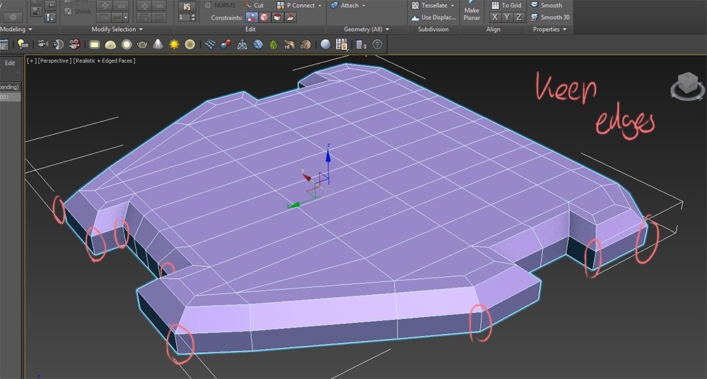
Hey! I've been struggling with this model. What would be a better topology for the normals to look good here? Especially the areas framed in orange. http://postimg.org/image/xc8edmlvr/
Hey! I've been struggling with this model. What would be a better topology for the normals to look good here? Especially the areas framed in orange. http://postimg.org/image/xc8edmlvr/
Xelloss, I'd first select all of your edges and change the smoothing angle of all of your edges. Once you've done that, add supporting edges to define the 'hardness' of your contours.
It's also a little hard to tell exactly how those highlighted areas are supposedto look, would you be able to embed it with sketchfab at all?
So i'm having trouble understanding something mentioned in this thread a while back (waay back) its about adding irregular details (edges) to cylinder (6 sided) and have it still subdivide into a "prefect" round cylinder. Here's the image The method of finding the location of the edges im sure is fine but i cant seem to understand how to connect them to the rest of cylinder without causing wobbly circle when subdividing, the problem i guess is that the distance between edges is now shorter and its causing the bulging but if i go and manually add edges it defeats the purpose of adding detail to single face right?
This is very cool and super useful technique, and i hope someone can help me with this, im sure its something obvious but it looks like i just cant see it.... Oh and im using maya if it makes any difference.
The keything is to move the edges you just added in the right direction(axis z edge normal), it will sure heal the shape, but never be perfect. Or you can just start with a cylinder that has more geo, more sides...
On the surface I would try using path deform binding modifier if you are using 3DS max. (other packages should have that but maybe under a different name)
Hi guys! I'm working on a helmet for an exam assignment.
I'm having trouble with the brown tube, more specifically, adding these waves.
As seen on the cylinder underneath, it is usually easy to get equal distance between 2 edges using the connect tool.
My method does not work using a spline, since the ditance between points is not equal. (see first picture!)
Is there a way for me to equally interpolate my entire spline ?
Thanks in advance for any help!
Hope this helps! This is how I approach objects like yours. Idk if a lot of people are really aware of the Snapshot feature, but it's so useful for those instances like where you have modifiers that must be in the stack for the effect to be applied. For example, converting to editable poly doesn't respect a Path Deform WSM, it just stays at the top of the stack if you try.
@WAYWO Yes, you are probably right.... i just found some interesting images from way back in this thread and gave them a go, i guess i totally forgot how the subd works, (averaging between vertices) and for a second, thought its a "miracle skeleton key" solution for subd modeling.
I tried to fiddle with the 6 sided cylinder some more to get it to subdivide into a circle, but nothing useful came out of it since, yes, the verts can be moved to make the smoothed version fit the circle, but its inaccurate, and too much eyeballing, compared to simply adding more sides and extruding the shape from them. I guess it wouldn't make any baking errors but still, i would know its not perfectly round
Hi there, i am new to this forum and work posted over here looks great. I am doing project for my university and my lecturer gave me advice to register over here and ask questions if i got stuck. I got this cylinder mesh over here pic1. Then i sort of extruded parts from it, everything is fine so far. I smooth it on pic2, and it goes smoothed. I am adding additional loops on the edge corners to compensate smoothness to leave extruded parts rough, but then it causes this "un-cylindrical" shape on picture 4 (marked as red). How can i change my topology to harden edges of extruded part and still having cylindrical shape of the rest? (This should be sort of torpedo hull) Thank you in advance.
when edges/points are too near each others, it create tension, crisp, crease, it's basic subD. Now what you can do is remove the edges where they create the non-desirable creases. and it'll slightly better already... again for further adjustments of the topology I'd show you this again !
How would you model this without deformer or nurbs or falloffs ?
Why do you want to limit yourself by not using one of these techniques?
I want to know how pure sub-d modeler works with double-curved. I use nurbs all the time with double curved so I wonder how people do this with poly manipulation and extrude.
1. Create a grid 2. Create a cylinder and try to match it up with the grid. By doing this you will have less geo to cleanup in the end. 3. Boolean! 4. Deform the resulting object by a lattice and weld some of the vertices to give a nice subd-topology.
As said before, there is no reson for trying to do it without a deformer. If you want to spend your time by moving points manually you can go for it. But there is no reason for doing it in this way...
Agreed. There's no reason to not use a deformer or nurbs in a sub-d workflow if those are the best tools for the job. Its like your a lumberjack not using a chainsaw because its not "pure lumberjacking" or something.
However, if you're asking how to do it in a program that doesn't support deformers or whatnot. I'd say make a half sphere with an odd number of segments. Delete all but the center segment. Duplicate that segment along a curve with the radius of the bottom curve of the shape so you get a sort of arch of arches. Draw an oval, or cylinder of the shape/radius of the top profile, and either cut around it or make a boolean intersection between it and the arch of arches. Weld the stray edge points in the resulting to their averages to solidify the object. (sorry for the lack of images. no modeling software here)
.WIKI Thanks for your input. I agree with your point. VAILIAS Thanks. I understand what you describe. It's the same as extrude curve profile on curve path then trim the surface to circle shape at top view.
I ask this question because I need to know if there is a better or equal way to make a controlled complex curve surface like saddle with poly modelling than with nurbs. I look around many forums and found out most people don't use nurbs (except industrial designer) which I found useful in this situation. So I want to see how experience poly modeler actually tackle problem like this.
sorry if it sounds like poly vs nurbs( but I am just really curious how everybody do things
i used a simple plane like below, just nudged some vertexes and its done super simple , booleaning etc i find it kind of a waste of time as you would need to cleanup alot of geo and be super hard to edit the shape incase you want to. But maybe i missed something.
I'm modelling a suit of armour and I was wondering if someone can help me figure out how to do this edge flow.
Old Low poly:
How it looks (like crap of course!):
Newer retopoly I've been doing:
I'm trying to make this a sub-d model. I think the newer one is better in terms of having a better amount and flow but I'm trying to think of how I can get nice embedded lines into it for the decoration. Would rather not use a normal map or w.e. for them. Part of the modeling challenge. Any tips/draw overs? Am I thinking about this wrong?
Guys, Im trying to remove a pinch from cylindrical shape. I tried few methods but all leave me with bigger pinching that was. It would be cool to get help with this as this specific shape gives me a headache all the time.
After few time trying to solve
This is how i left it. The pinching is small but still is bugging me
Also Im trying to work out topology on this one so Turbosmooth would work with out pinching. Any thoughts?
That has been answered so many times in this thread, I suggest you look back and have a look. Specifically at Perna's posts.
That has been answered so many times in this thread, I suggest you look back and have a look. Specifically at Perna's posts.
Cookedpeanut, I am aware that it was answered and probably somewhere on start but for some reason cant see any images from the start to around 15-30 pages. Anyway atm im going backwards from 201 and only got to 175 so still a bit of digging to go through Dunno maybe my internet is bad.
Replies
Select object you want to duplicate, use the spacing tool, select spline you just made, mess with parameters till it looks right.
pro: you keep the spline for further use
Con: more steps and more fiddly than shown in the video.
There's no need to keep something like a fence as a single contiguous mesh.
or the long way
Second: Here's a hint: its a 2 Möbius strips with a cork in the top.
The problem is punching a hole in this braided half-torus. The model was created from the red shape in pic 1 by extruding, twisting and bending. As you can see in pic 3, this makes all the originally square polys into slanted rectangles.
Cutting the hole before twisting and bending will obviously result in a twisted hole.
Booleans will make a mess because of the rectangular slanted polys.
yeah but have you tried fixing the topology by hand after bolean-ing ?
Heyho,

my problem is in some ways similiar to MAELSTROM7A's problem. I tried to model a curved line in around a slightly stretched sphere and create a High Poly with Turbo Smooth in Max. First i used the twist modifier to get the curve into the topology, but the shading with this edge flow wasn't good because the Quads got twisted too much. So i just extracted some Geo from the twisted Sphere and tried to merge into a not twisted sphere. Turbo Smooth now creates some dents were i tried to connect the two geometries rounded geometry. I tried different approaches on how to go about this, as you can see in the lowpoly topology, but nothing seemed to give good results. Does Anybody have an idea how to fix those dents from the irregular topoflow or how to model this kind of Geometry in a better way?
Your help is very much appreciated
best regards
Hanschi
Second: I cannot fathom why you'd have a pole sticking through the middle of a braid of rope or cable like that (assuming that's what it is), but you can achieve it by making a circle spline the same size as your pole, switching into an orthographic view facing that circle, then using the cut tool on the rope object to inscribe new edges into your object. You'll need to clean up the verts and polys near the hole, but that just comes with the territory. You can also try using the boolean tool with the "CUT" operation selected. It should do the same thing.
If it was simply a problem of cutting a hole in a mesh I wouldn't have bothered you guys. Hopefully after 200 pages we all know how to do it. As I said the problem is the weird topology. The hole will also come out on the other side of the mesh, and maybe end up in the middle of a pole. Then there are the polys flowing upward, causing artefacts.
I've tried dozens of ratios of loops/edges, various twisting amounts, etc. Artefacts and screwed up topologies is all I came up with.
Hi, I've done little to no sub-d before and am getting some practice in. What's causing those ridges?
i hope you dont mind me asking this basic stuff, but i need some advise:


i want to make a high-poly version of this object and usually i apply some swiftloops around the edges to keep them nice and round.
but on certain meshes this seems to end in a very chaotic topology, my question is, is something wrong with my base approach in modelling the topology?
here is my low-poly object:
i tried with swift-loops
best and easiest way seems to be to just tesselate alot and turbosmooth after
http://postimg.org/image/xc8edmlvr/
It's also a little hard to tell exactly how those highlighted areas are supposed to look, would you be able to embed it with sketchfab at all?
So i'm having trouble understanding something mentioned in this thread a while back (waay back) its about adding irregular details (edges)
to cylinder (6 sided) and have it still subdivide into a "prefect" round cylinder. Here's the image
The method of finding the location of the edges im sure is fine but i cant seem to understand how to connect them to the rest of cylinder
without causing wobbly circle when subdividing, the problem i guess is that the distance between edges is now shorter and its causing the
bulging but if i go and manually add edges it defeats the purpose of adding detail to single face right?
This is very cool and super useful technique, and i hope someone can help me with this, im sure its something obvious but it looks like i just
cant see it....
Oh and im using maya if it makes any difference.
Hi guys! I'm working on a helmet for an exam assignment.
I'm having trouble with the brown tube, more specifically, adding these waves.
As seen on the cylinder underneath, it is usually easy to get equal distance between 2 edges using the connect tool.
My method does not work using a spline, since the ditance between points is not equal. (see first picture!)
Is there a way for me to equally interpolate my entire spline ?
Thanks in advance for any help!
Hope this helps! This is how I approach objects like yours. Idk if a lot of people are really aware of the Snapshot feature, but it's so useful for those instances like where you have modifiers that must be in the stack for the effect to be applied. For example, converting to editable poly doesn't respect a Path Deform WSM, it just stays at the top of the stack if you try.
Thank you very much!
Worked like a charm!
I tried to fiddle with the 6 sided cylinder some more to get it to subdivide into a circle, but nothing useful came out of it since, yes, the verts can be moved to make the smoothed version fit the circle, but its inaccurate, and too much eyeballing, compared to simply adding more sides and extruding the shape from them. I guess it wouldn't make any baking errors but still, i would know its not perfectly round
anyways thanks for the reply, much appreciated.
The script (modifier) for creating holes from the vertices.
How would you model this without deformer or nurbs or falloffs ?
1. Create a grid
2. Create a cylinder and try to match it up with the grid. By doing this you will have less geo to cleanup in the end.
3. Boolean!
4. Deform the resulting object by a lattice and weld some of the vertices to give a nice subd-topology.
As said before, there is no reson for trying to do it without a deformer. If you want to spend your time by moving points manually you can go for it. But there is no reason for doing it in this way...
However, if you're asking how to do it in a program that doesn't support deformers or whatnot. I'd say make a half sphere with an odd number of segments. Delete all but the center segment. Duplicate that segment along a curve with the radius of the bottom curve of the shape so you get a sort of arch of arches. Draw an oval, or cylinder of the shape/radius of the top profile, and either cut around it or make a boolean intersection between it and the arch of arches.
Weld the stray edge points in the resulting to their averages to solidify the object.
(sorry for the lack of images. no modeling software here)
Thanks for your input. I agree with your point.
VAILIAS
Thanks. I understand what you describe. It's the same as extrude curve profile on curve path then trim the surface to circle shape at top view.
I ask this question because I need to know if there is a better or equal way to make a controlled complex curve surface like saddle with poly modelling than with nurbs. I look around many forums and found out most people don't use nurbs (except industrial designer) which I found useful in this situation. So I want to see how experience poly modeler actually tackle problem like this.
sorry if it sounds like poly vs nurbs( but I am just really curious how everybody do things
I don't know it could be done this easily. I should go study how think like poly modeller asap.
Old Low poly:
How it looks (like crap of course!):
Newer retopoly I've been doing:
I'm trying to make this a sub-d model. I think the newer one is better in terms of having a better amount and flow but I'm trying to think of how I can get nice embedded lines into it for the decoration. Would rather not use a normal map or w.e. for them. Part of the modeling challenge. Any tips/draw overs? Am I thinking about this wrong?
It would be cool to get help with this as this specific shape gives me a headache all the time.
After few time trying to solve
This is how i left it. The pinching is small but still is bugging me
Also Im trying to work out topology on this one so Turbosmooth would work with out pinching. Any thoughts?
Dunno maybe my internet is bad.