The BRAWL² Tournament Challenge has been announced!
It starts May 12, and ends Oct 17. Let's see what you got!
https://polycount.com/discussion/237047/the-brawl²-tournament
It starts May 12, and ends Oct 17. Let's see what you got!
https://polycount.com/discussion/237047/the-brawl²-tournament
Best Of
Re: What made you feel good today?
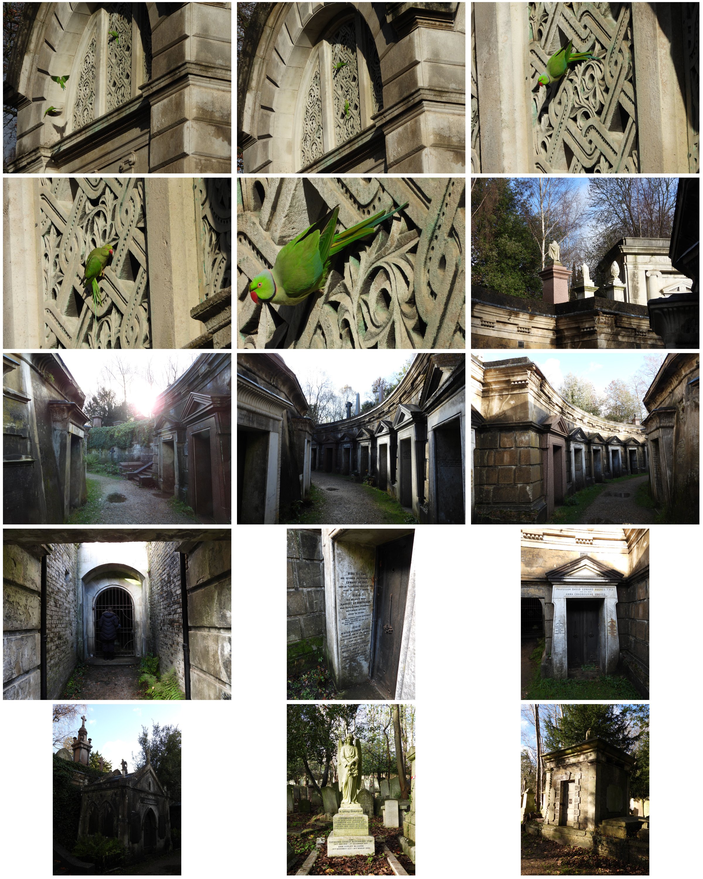
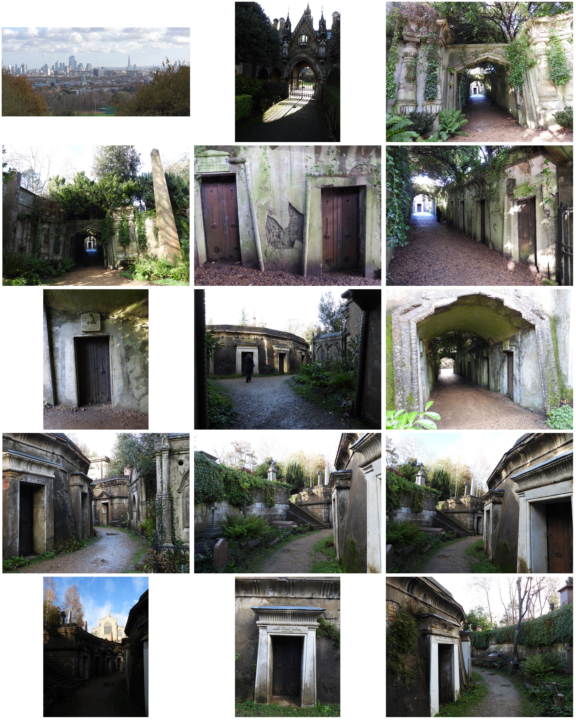
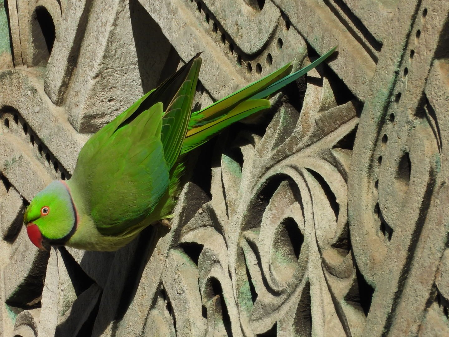
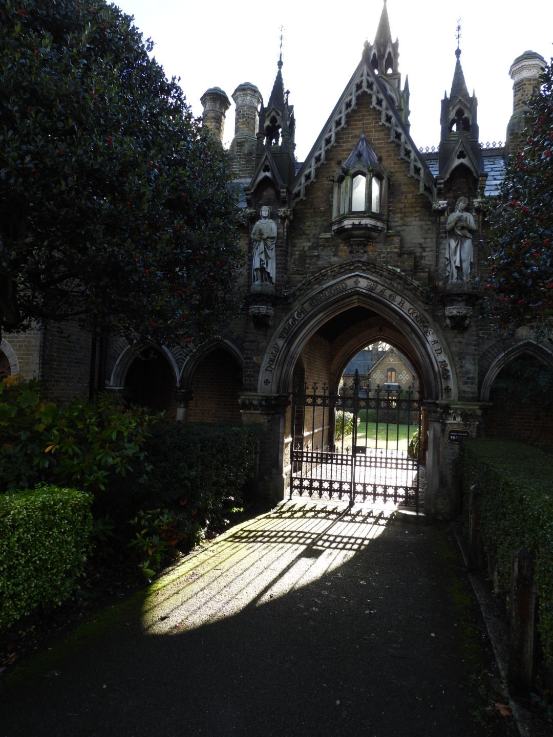
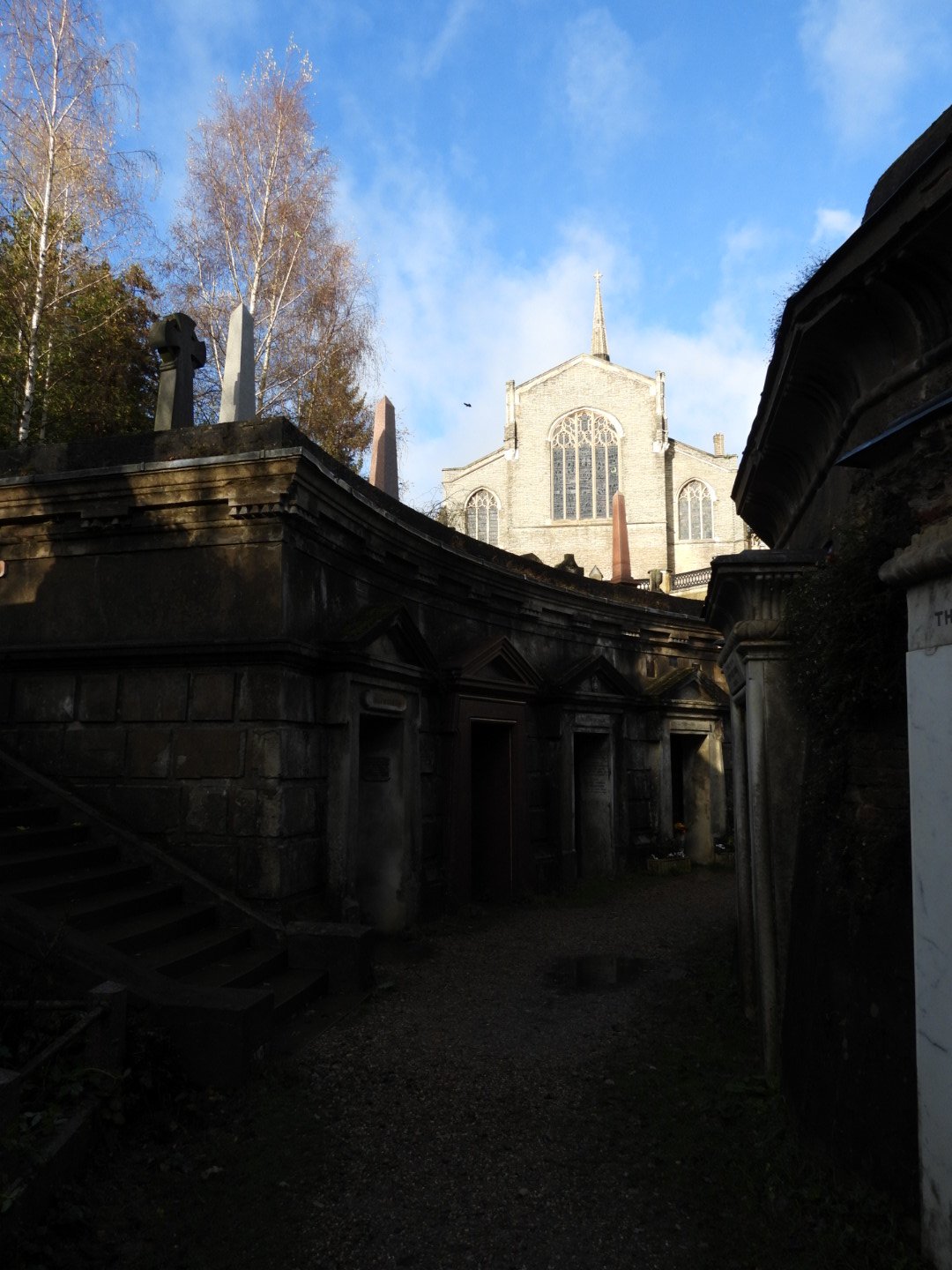
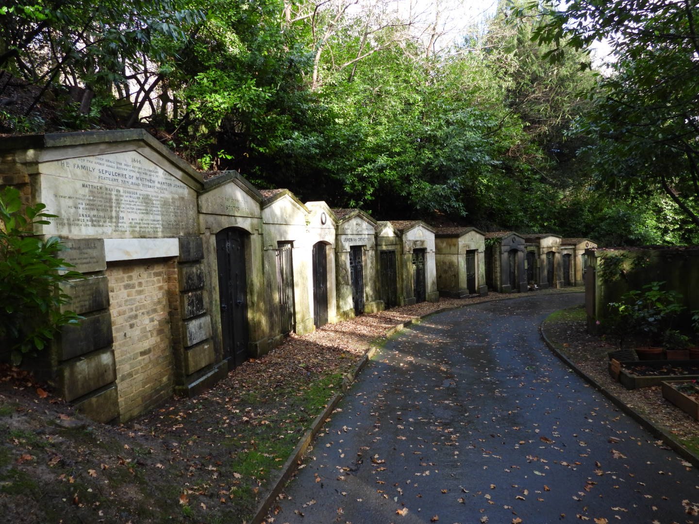
I went for a walk about in a place called highgate cemetery in London, I know its a bit morbid but its a very interesting place, I saw some feral parakeets which are growing in number, they definitely give London wild life a touch of colour, lol! ")

 littleclaude
4 ·
Re: The Bi-Monthly Environment Art Challenge | November - December (99)
Hi folks I'm back! Took a break because of Thanksgiving.
I got to the texturing part finally! I'm running into some issues though. This time I focused mostly on the base of the model, I used a Smart Material to start off and added some of my own things in there and tweaked things a bit. Added color variation and a subtle height map with some bumps, as well as AO.


I also added some decals and normal details like the rivets and screws. I want to add even more dirt/grime to this.

I got some artifacts in the bake and I'm not sure how to fix them. They're not particularly egregious but if I can prevent them from happening again, that would be great, so if anyone has any tips on baking, please send them my way!

I added another smart material that I plan on modifying to the canisters, but didn't get a chance to tweak them. Overall I spent about 3 hrs within the texturing process so far. A lot of that time was spent playing with the brushes, decals, and trying to figure out the vertex colors thing.
I used vertex colors but forgot how to use them while texturing... *sigh* I'll just have to go have a look at the tutorial again.
Unfortunately I told myself I wouldn't spend longer than a week on this project and thus, I will have to stop this here for now. I got frustrated with the textures and realize I have to recap the tutorials I watched, so I can jump in again. However, I really need to move on to a different project as of now. BUT I WILL BE BACK and finish this, I'm literally so close to finishing it, how could I not? I'll probably have to give updates on a separate thread once this one closes for the challenge.
Anyway, cheers to all those working on the challenges! (I think just you @Fabi_G and me?)
I got to the texturing part finally! I'm running into some issues though. This time I focused mostly on the base of the model, I used a Smart Material to start off and added some of my own things in there and tweaked things a bit. Added color variation and a subtle height map with some bumps, as well as AO.

I also added some decals and normal details like the rivets and screws. I want to add even more dirt/grime to this.
I got some artifacts in the bake and I'm not sure how to fix them. They're not particularly egregious but if I can prevent them from happening again, that would be great, so if anyone has any tips on baking, please send them my way!
I added another smart material that I plan on modifying to the canisters, but didn't get a chance to tweak them. Overall I spent about 3 hrs within the texturing process so far. A lot of that time was spent playing with the brushes, decals, and trying to figure out the vertex colors thing.
I used vertex colors but forgot how to use them while texturing... *sigh* I'll just have to go have a look at the tutorial again.
Unfortunately I told myself I wouldn't spend longer than a week on this project and thus, I will have to stop this here for now. I got frustrated with the textures and realize I have to recap the tutorials I watched, so I can jump in again. However, I really need to move on to a different project as of now. BUT I WILL BE BACK and finish this, I'm literally so close to finishing it, how could I not? I'll probably have to give updates on a separate thread once this one closes for the challenge.
Anyway, cheers to all those working on the challenges! (I think just you @Fabi_G and me?)
 fairlyBread
4 ·
Re: Stylized Stubby Flintlock Pistol (WIP)
Where it all began.
This model started as an entry for a fun one week Blender challenge at uni, themed "Pirates".
My initial concept-art.

The final render for the challenge, with a bevel modifier on it for a quick'n'dirty mid-poly.

The low-poly model.
 domfiglhuber
3 ·
Re: The Bi-Monthly Environment Art Challenge | November - December (99)

@Fabi_G
I checked out your latest build! I love the the footsteps! Nice detail.
Oh and the polycount shoutout!

It was a pleasure to be in this challenge with you. Great work and good luck out there in the pixelated world!
fairlyBread
5 ·


[WIP] Stylized Island (for portfolio)
Hey whats up Polycount,
I’m working on a portfolio piece — a stylized island environment. (inspiration, sea of thieves) I’ve been focusing on blockout, and overall playability for the past couple of days. scaled to SoT
I’d love feedback on:
Shot composition (do any of these even look ok) I feel like im going crazy or missing something. not sure how to shoot an island for presentation in a portfolio.
Focal points & balance advice?
Here are some quick view port screenshots. Any thoughts while I get to modeling would be super helpful!
I just seam to be lost in the sauce of shooting an island ( anything else that sicks out? let it rip please! )


Thank you a ton!
 HolySour
3 ·
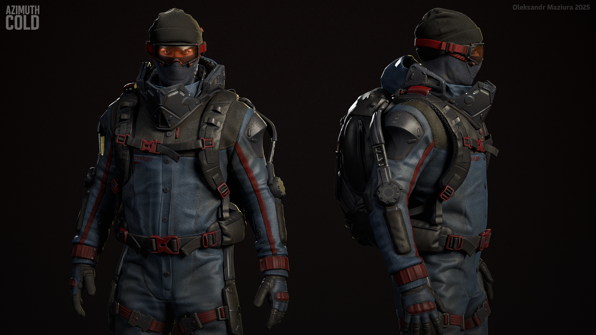
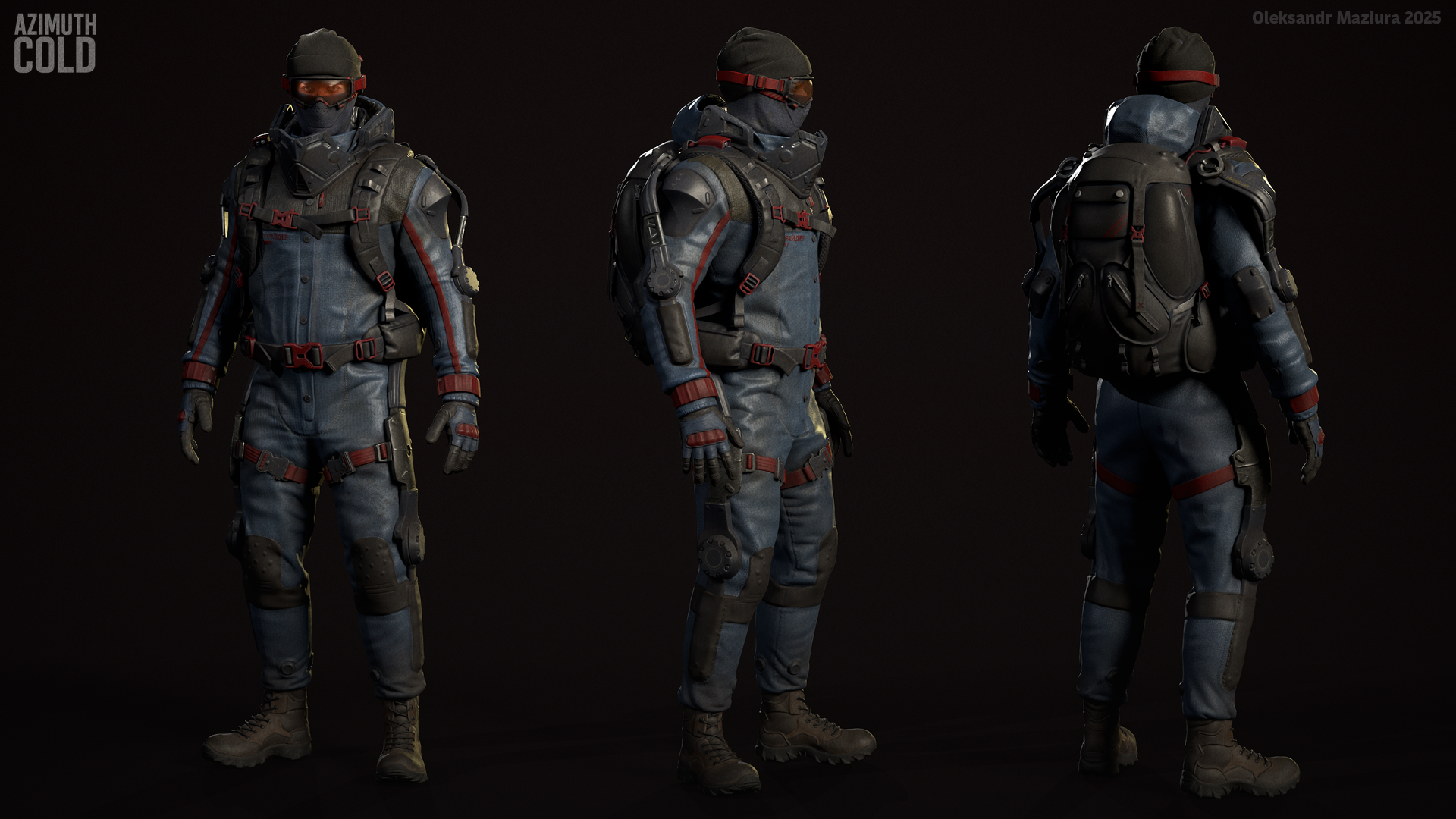
Re: Azimuth Cold - FPS game visual prototype
Made basic setup in UE5, added pick up and inspect animations.
some polishing required, but for now I am moving forward
 Sigmatron
4 ·
Re: The Bi-Monthly Environment Art Challenge | November - December (99)
Thanks for pointing this out Eric  didn't fix this in the latest build yet, but it's on my list!
Two screenshots of the latest build:


Some notes on what I did:
Footsteps
Two screenshots of the latest build:
Some notes on what I did:
Footsteps
Get spawned by an animation event. At first I applied them as decals, but when I used some displacement on the sand, the displacement wouldn't get taken into account, the footsteps essentially disappearing. Possibly there is a setting/ way to make it work. However the approach I took then, was to place another camera above the play area and assigned a render texture to render to. Then, I spawned footsteps with a grayscale texture, which would blend to white over time. In the sand material, I input the render texture, convert it to a normal map, which is combined with the base normal map. Probably there are smarter/ more performant solutions I yet have to discover :P
Cloth movement
Since I couldn't get the cloth sim look stable in build (and painting the cloth mask was a pain, broke whenever I updated the mesh), I opted to just add some subtle movement by displacing the mesh some vertically, limited by vertex color mask.
Bounce light from sand
While I increased the indirect lighting contribution of the main lights, the bounce-light felt too subtle. I added some more by placing some area lights below the sand and added a 'bakery light mesh' component to the sand skirts. I also added another non-shadowcasting directional light, just affecting the figure to light it up from below, as light was reflected from the sand. I first tried doing this effect in the shader, but couldn't make it look good. For the sand material, blended in a macro texture to lessen visible tiling (well, it's same texture with a different UV scale) by a sphere mask from camera pos. Switching between two radius values based on what camera is active.
Light source
Added a light-source emitting a blueish light. It has a non-shadowcasting component just affecting the figure and a baked component for the static environment. Created a simple sprite sheet in Photoshop, to be used by a particle system.
What do I want to do next? Flesh out the area around the light, add some moving/ flowing/ falling sands elements, improve structures, improve figure.
 Fabi_G
4 ·
Re: What Are You Working On? (3D) 2025
Trying to figure out if I still remember how to do environment art.
Making master materials and shaders and whatnot. it has been a while.
All feedback is welcome, especially bad ones.

Making master materials and shaders and whatnot. it has been a while.
All feedback is welcome, especially bad ones.
4 ·
Azimuth Cold - FPS game visual prototype
I know fellas how you're missed threads with my projects ")
It's time for me to look for a job, so I decided to refresh portfolio with a new artwork. My goal here is to create a
character for my UE5 FPS "game" Azimuth Cold, which will be a real
portfolio piece. It will include character, weapon, fpv animations,
setup in UE5, demo level and some basic shooter mechanics, so it will
look like a real game.
I will tell more about the project in a visual way with new content in the next posts
Cheers!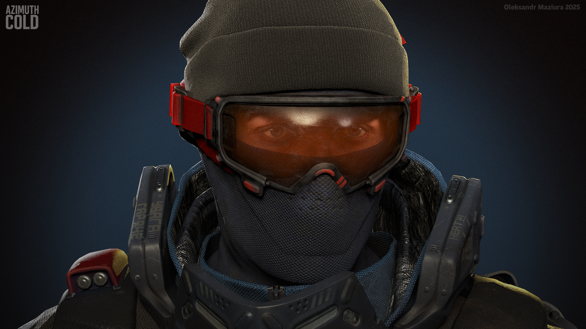
I will tell more about the project in a visual way with new content in the next posts
Cheers!
Aaand artstion: https://www.artstation.com/artwork/DLRGKR
Sigmatron
3 ·