Best Of
Re: Do you think polycount a dying platform?
I am so happy that Polycount still exists and keeps the old-school raw interaction alive. After many years, I've canceled all my social media accounts (because of the noise of stupid people, AI slop, politics, Blender influencers, bots...) and found a place here. According to the current situation on the internet, I think Polycount has a very bright future.
 ondrejmalota
3 ·
Re: Having doubts about taking a first job landing
you should delete their email and block them. That ain't an opportunity nor a foot in the door. That's literally modern day slavery bro. Make more art, post more art, get actual, real opportunities
 zetheros
3 ·
Re: [WIP] Miss Peregrine - Eva Green Likeness (Realtime)
Legends speak of a man who was recently part of a studio closure. He returned to a 4 year old WIP thread in the ancient temple where the the greatest of the 3D wizards honed their craft for years. He hoped once more to draw upon its magical essence and wield it to complete long unfinished tasks.


 RabidRabit
4 ·
Re: Show your hand painted stuff, pls!
A small hand painted project done for practice.
Concept: Betty Jiang
Model & Texture: Alfredo Santos
Concept: Betty Jiang
Model & Texture: Alfredo Santos
 frodin
5 ·
Re: Show your hand painted stuff, pls!
Recently finished this as a bit of practice for meeting deadlines, and just finishing a project without noodling too much. I didn't quite meet my first goal, but I did manage to finish this significantly faster than other, similar projects. Also my first actual post here - so hopefully more where this came from!

 Tom_Axler
4 ·
Re: Sketchbook: Frank Polygon
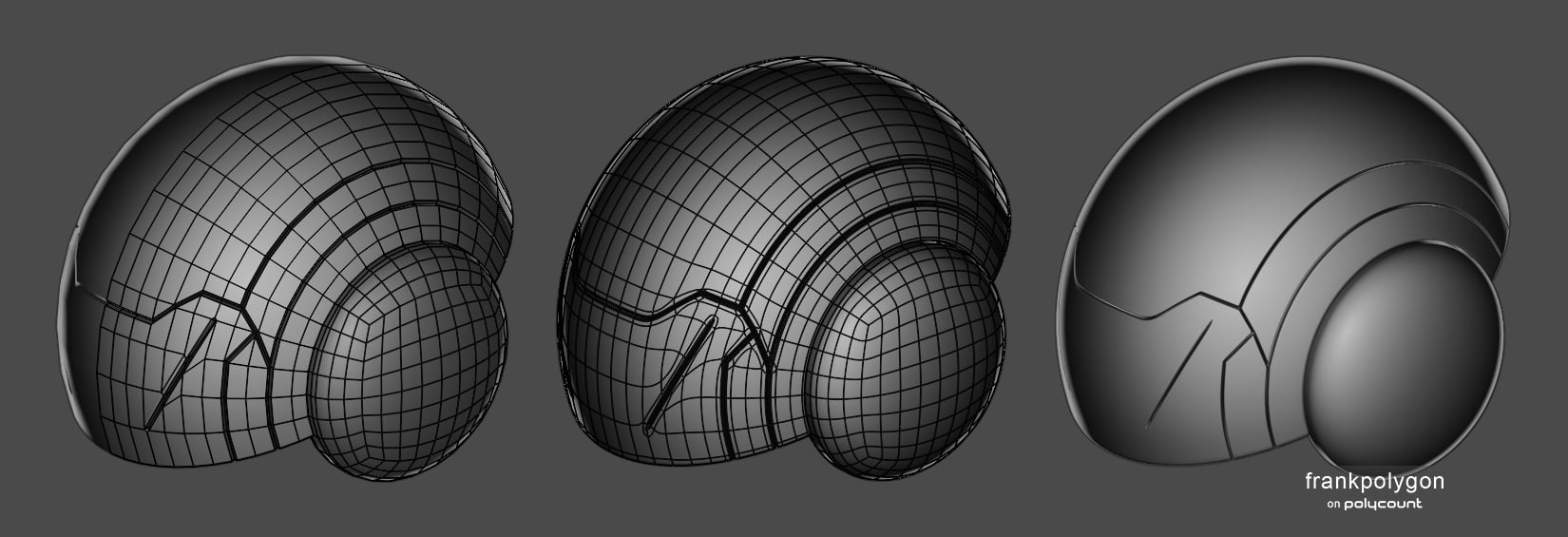
Subdivision sketch: Hemispherical helmet.
This is a brief look at a few basic strategies for routing topology around cut outs and panel lines on spherical [and ellipsoid] surfaces.
Note: there's several different ways to structure spherical geometry. Since this write-up is specific to basic subdivision modeling only basic spheres and quad spheres are mentioned.
Basic spheres, with one vertex at each pole, provide a lot of control over segment spacing but also tend to produce smoothing artifacts near the caps because all of the edges there converge at a single point. While there are a few ways to reduce or resolve the smoothing artifacts on basic spheres, quad spheres have eight evenly distributed N poles and a fairly even quad grid topology that often make it a better choice for subdivision modeling.
Quad spheres subdivide cleanly but there are still some downsides. The layout of the quad grid is fairly inflexible and most tools generate quad sphere primitives with 24 faces then increase the mesh density by subdividing. Which means the density of the mesh increases four times for every subdivision level applied. The lack of fine control over the number of segments and rings means the density will often be a bit less or bit more than what's optimal.
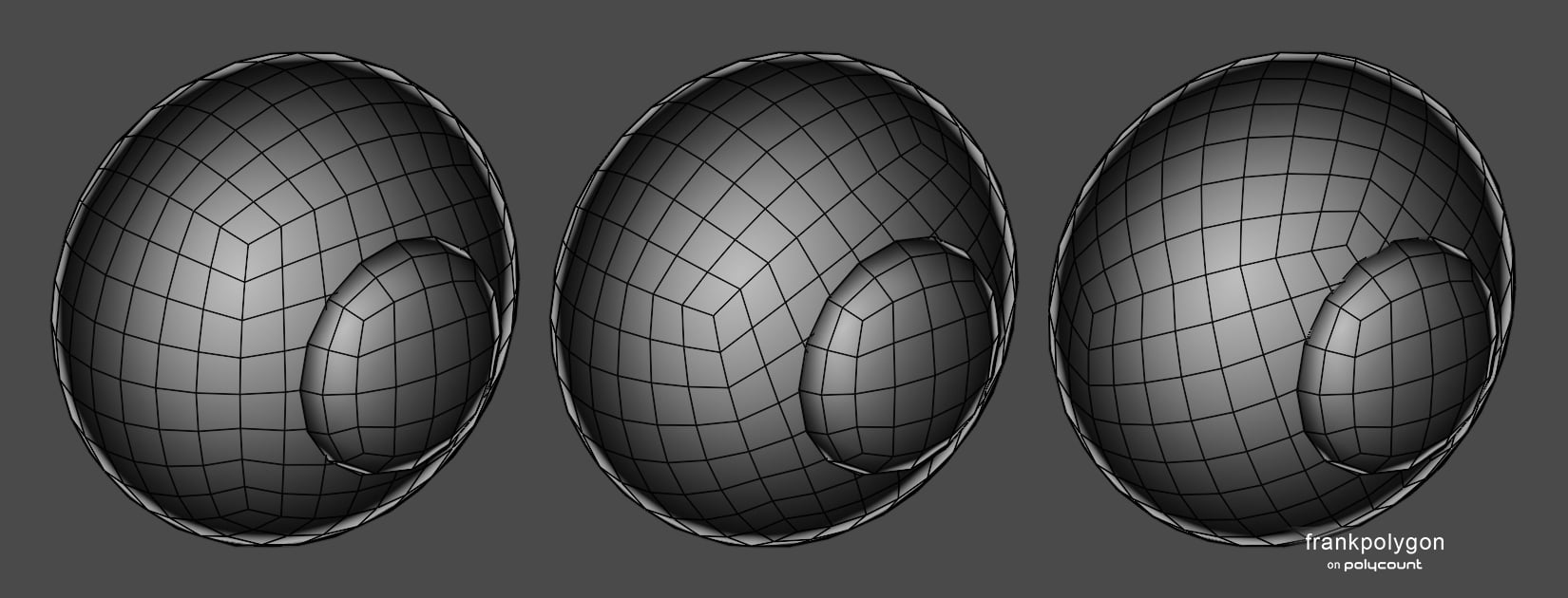
When modeling with quad spheres it's important to orient both the grid and poles so the topology flow matches the larger primary forms and provides support for the smaller secondary forms and tertiary details. Especially when these shapes intersect the surface of the sphere.
The example below shows how simply rotating the larger quad sphere changes the relative topology of the underlying surface. Going from a linear square grid that runs vertically and horizontally to one that runs diagonally and forms a diamond pattern. Simply rotating the underlying geometry so it aligns with the intersecting shapes can prevent a lot of headaches caused by messy topology and unnecessary manual clean up work.
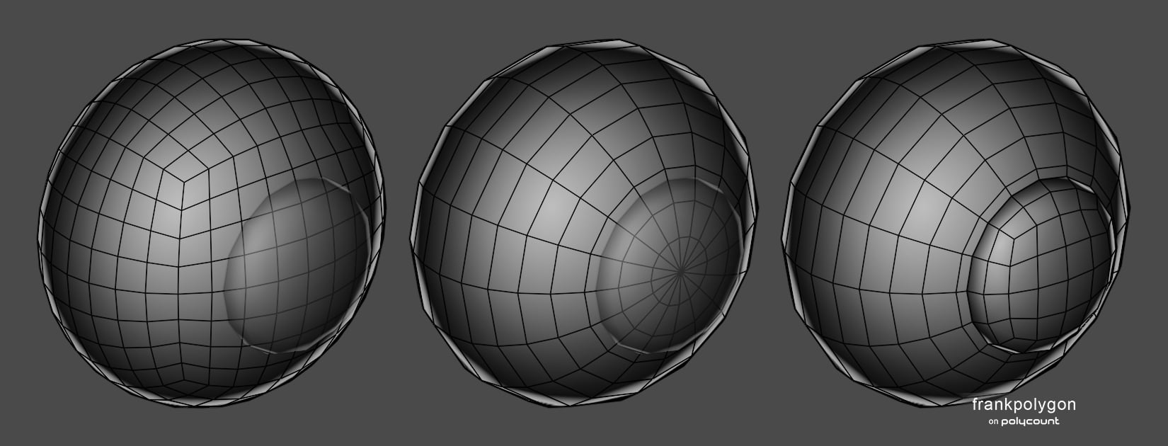
It's also possible to combine the different positive aspects of both basic spheres and quad spheres in a way that avoids the inflexibility of the quad sphere and resolves the smoothing artifacts on the caps of the basic sphere.
Here's an example of how simply rotating the basic sphere so the poles are hidden beneath the intersecting shape allows it to be capped with an ellipsoid made from a quad sphere.
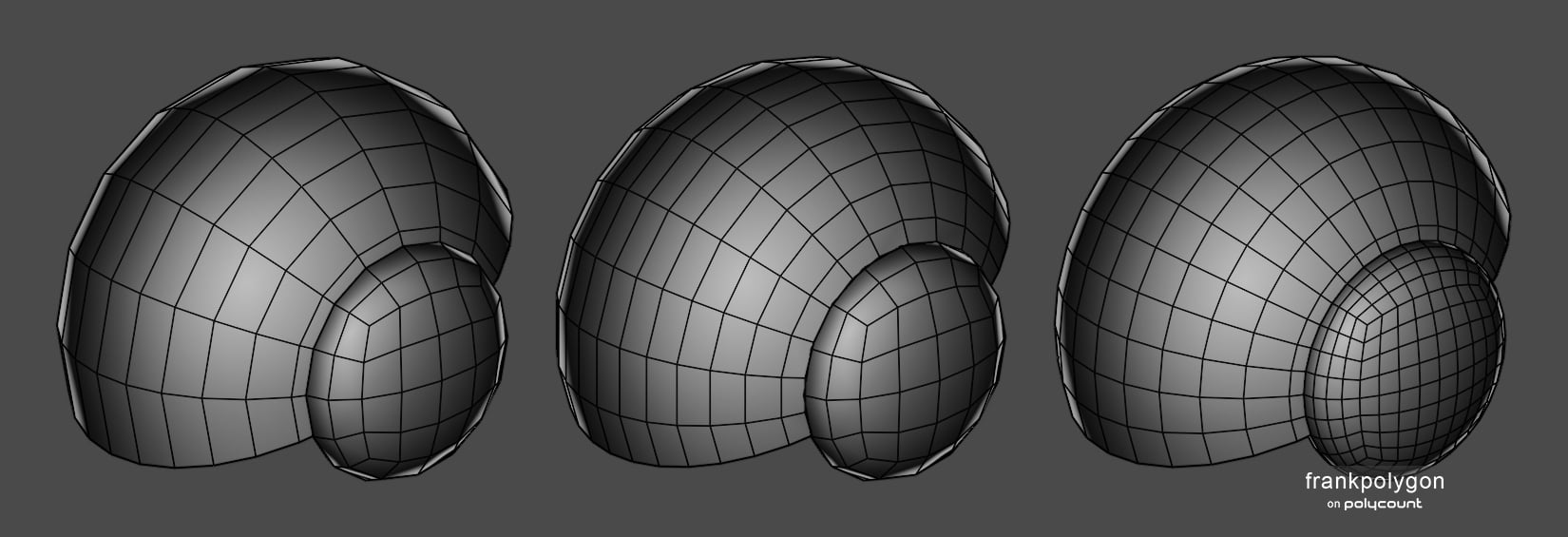
When modeling something like this helmet only part of the sphere is needed and there's often cut outs or protrusions around the ears. So use those natural breaks or changes in the shapes to redirect the loop flow.
It's also helpful to break complex objects down and model the parts individually. Since this allows for localized differences in mesh density and topology flow. If it doesn't need to be connected in a watertight mesh then model it separately.
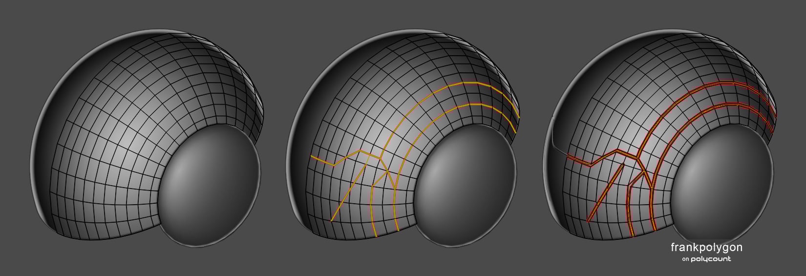
Sometimes disrupting the segment spacing and topology flow is unavoidable when cutting in panel lines. While it's possible to manually compensate for this by adjusting the relative height of the new edges between the segments of the curve it often makes more sense to just shrink wrap everything onto a clean guide shape.
The example below shows how the basic shape acts as a guide and most of the panel lines follow the existing geometry but where ever they cross over diagonally the geometry is re-projected onto the clean shape below it to remove any unwanted deformation and maintain the desired surface quality.
Once the basic loop paths are established a manual bevel / chamfer operation is used to create the geometry for the panel lines and the edges in the center of those loop paths are moved below the surface to create depth.
Once the basic loop paths are established a manual bevel / chamfer operation is used to create the geometry for the panel lines and the edges in the center of those loop paths are moved below the surface to create depth.
Here's what the final high poly looks like. The editable base mesh is fairly simple, all of the support loops are added around the panel lines with a bevel / chamfer modifier and the entire surface of the helmet follows the underlying guide shape using a shrinkwrap modifier. This keeps everything in the final high poly nice and crisp but still easy to work with.
There's different ways to approach adding more complex shapes and cleaning up the topology. So it just comes down to applying the same basic principles through a bit of trial and error. Even with this less than ideal topology layout the shading is more than acceptable because the surface conforms to the guide shape.
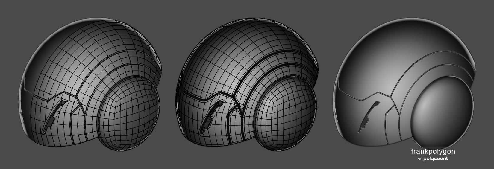
Highly reflective surfaces have to be just right or visible surface quality artifacts will start to appear. Using a guide shape and shrink wrap modifier makes finding minimum viable a lot quicker and it's easier to clean up the topology without having to constantly re-work large sections of the mesh to maintain the accuracy of the shapes.

Recap: Choose a sphere's topology layout based on how it fits the forms and rotate the geometry so it lines up with any intersecting shapes. Simplify a complex model by creating it from individual pieces with varying geometry densities. Try to maintain consistent segment spacing between the edges that make up curved surfaces but whenever that's not possible manually compensate for unwanted deformation and consider shrink wrapping everything to a clean guide shape to preserve the surface quality.
Below are a few links to other write-ups that cover various topology issues on hemispherical shapes.
Panelizing:
https://polycount.com/discussion/comment/2769890#Comment_2769890
https://polycount.com/discussion/comment/2741997/#Comment_2741997Panelizing:
https://polycount.com/discussion/comment/2769890#Comment_2769890
https://polycount.com/discussion/comment/2745072#Comment_2745072
https://polycount.com/discussion/comment/2771704#Comment_2771704
Sphere topology:
https://polycount.com/discussion/comment/2733850/#Comment_2733850
https://polycount.com/discussion/comment/2774300#Comment_2774300
Shapes intersecting spheres:
https://polycount.com/discussion/comment/2800738/#Comment_2800738
https://polycount.com/discussion/comment/2745029/#Comment_2745029
https://polycount.com/discussion/comment/2743152/#Comment_2743152
https://polycount.com/discussion/comment/2733818/#Comment_2733818
https://polycount.com/discussion/comment/2777813#Comment_2777813
https://polycount.com/discussion/comment/2777595#Comment_2777595
https://polycount.com/discussion/comment/2777595#Comment_2777595
Basic helmet shapes:
https://polycount.com/discussion/comment/2771703/#Comment_2771703
https://polycount.com/discussion/comment/2806840/#Comment_2806840
5 ·
Re: Sketchbook: Frank Polygon
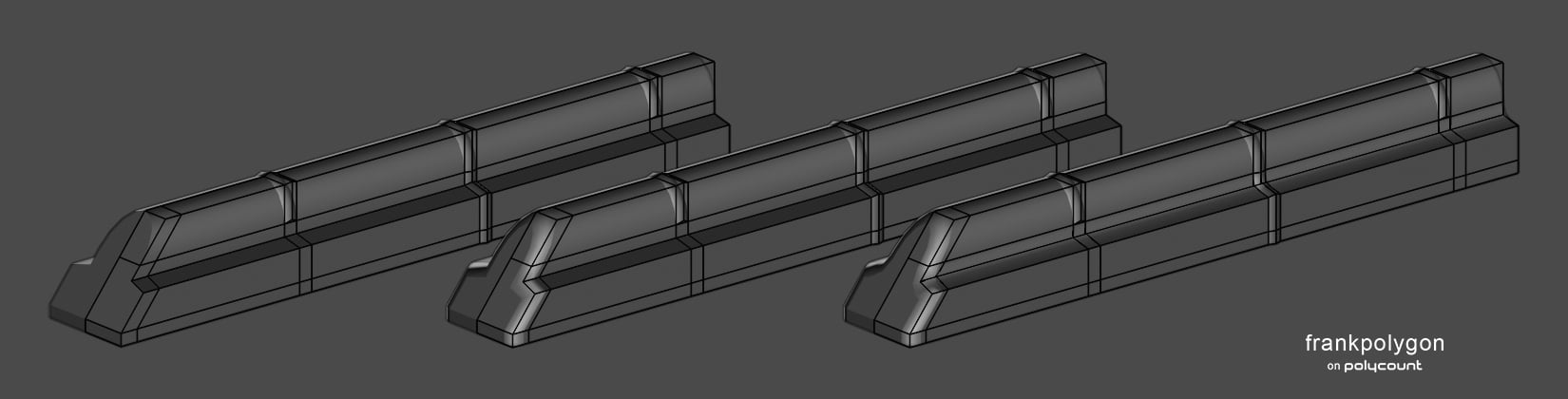
Subdivision sketch: Dust cover.
Another quick look at a more streamlined approach to shape first block outs and subdivision modeling.
Create the basic shapes and cut in the basic loop routing for secondary forms that interact with the curvature on the primary forms. Keep everything relatively simple and focus on creating accurate proportions while also planning out basic loop routing paths for curves and intersecting shapes.
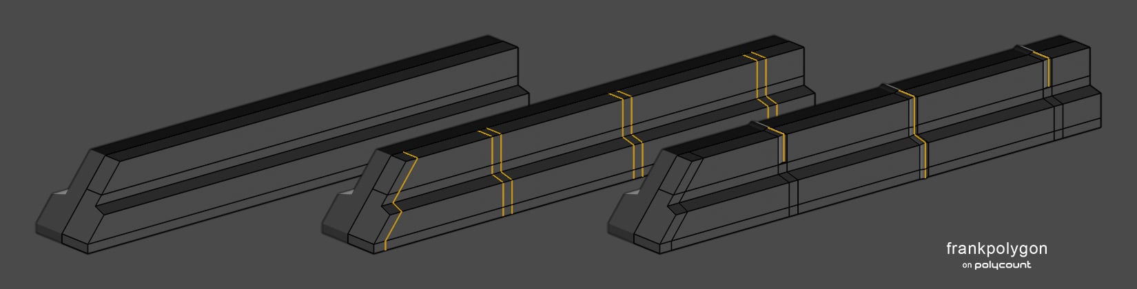
Define the fillets and round overs with a series of bevel / chamfer operations. Assign each operation to individual modifiers for non-destructive editing of the shape profile and segment spacing on the primary forms. This way any changes to the larger forms automatically carry over to the smaller, curved secondary forms until each modifier is applied.
Outline the larger secondary details by cutting in additional loop paths then use those loop paths form the cut outs in the primary forms.
Simplify the loop paths and adjust the segment density of the curves to support smaller tertiary details as necessary.
Apply individual bevel / chamfer modifiers as required when adding tertiary details. Add a solidify modifier to create the internal faces and edge depth.
Additional write-ups that cover similar shapes and using modifiers to streamline subdivision modeling:
https://polycount.com/discussion/comment/2804901/#Comment_28049014 ·
Re: Sketchbook: Frank Polygon
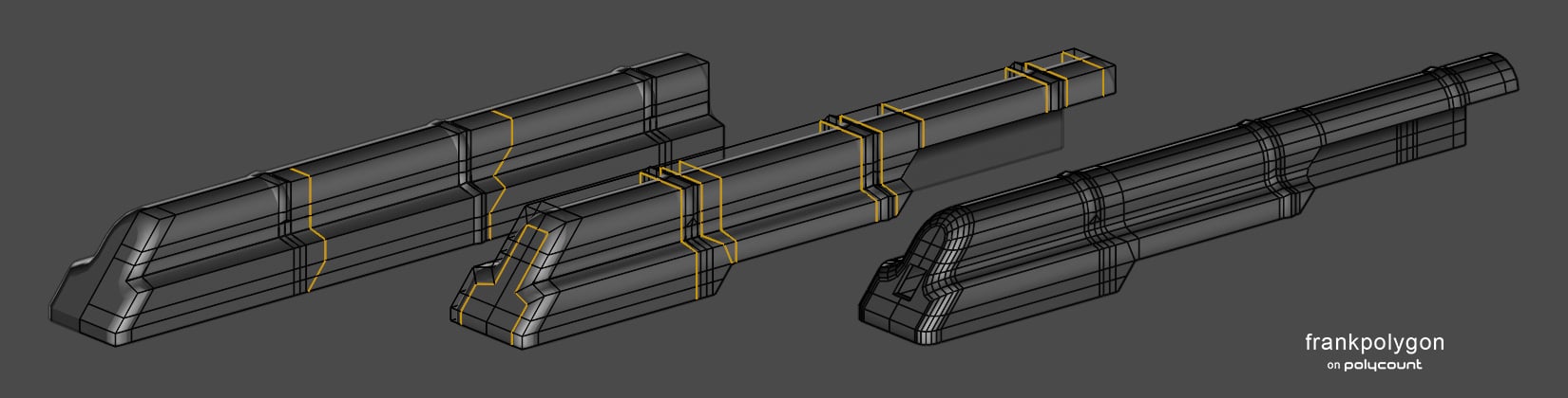
Subdivision sketch: Charging handle.
A quick look at a shape first approach to modeling something with complex compound curves.
Start by blocking out the overall volume of the part and use that mesh to figure out a basic loop routing pattern for the rest of the forms. Continue developing the block out by outlining the larger primary forms first then move on to defining the shape and segment density of the smaller secondary forms.
Focus on creating the curves in the primary forms, from largest to smallest, before cutting in any secondary forms that intersect areas with compound curvature. Try to use the existing geometry in the curves to support any intersecting shapes and maintain consistent edge spacing along each curved surface to avoid unwanted deformation when subdividing the mesh.
Below is an example of what block out process could look like.

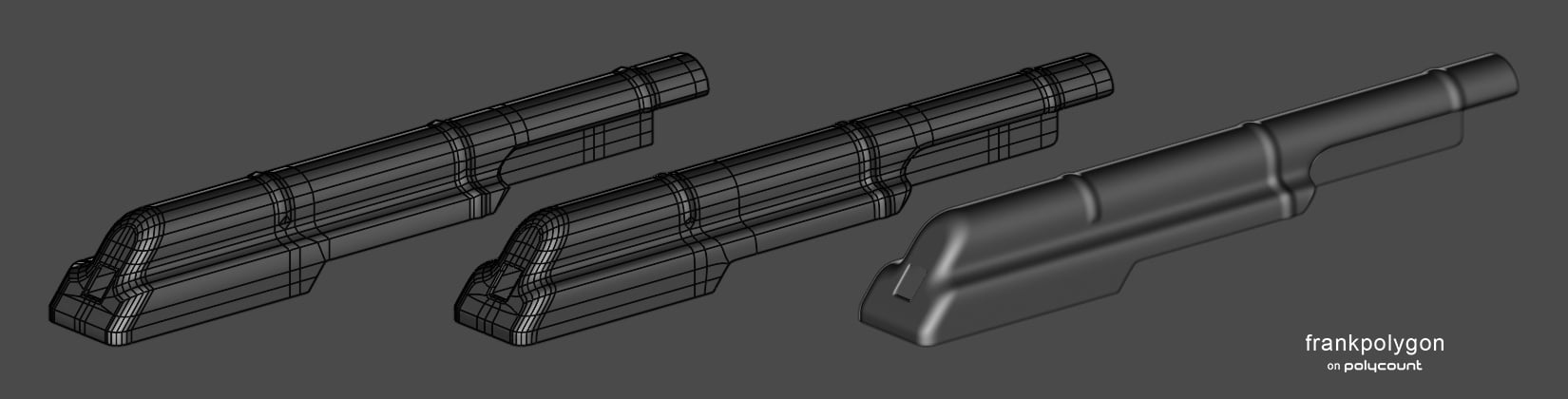
Simplify the base mesh and let the outside edges of the shapes define where the final highlight sharpening support loops go. In this example all the support loops were added with a single bevel / chamfer operation that can be easily automated with a modifier driven by edge weights or face angle.
In some situations it may be necessary to adjust the position of individual vertices to compensate for smoothing stress around support loops.

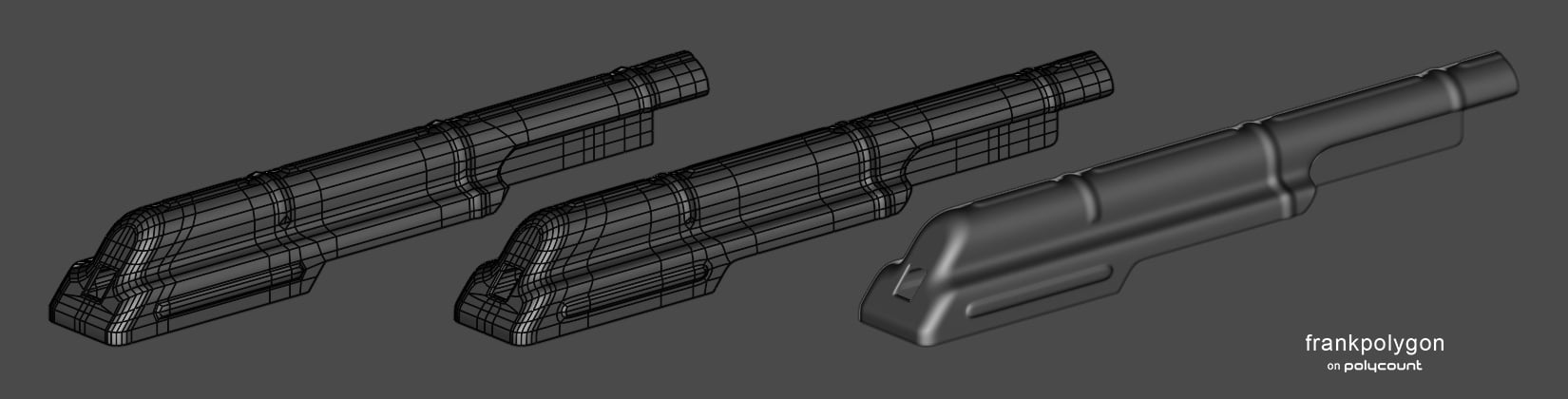
Here's what the final base mesh and high poly look like. There are a couple of n-gons that could be resolved by adding a loop cut or triangulating them but, for most high to low game art workflows, as long as the mesh subdivides cleanly that's more of a minor technical compliance issue than anything else.

Clean topology is important but adding too many support loops too early can easily over complicate a base mesh. Which often results in more time spent wrangling the edge loops than developing the underlying shapes.
So keep the mesh relatively simple at first and focus on fundamentals like creating accurate shapes and maintaining
consistent segment spacing on curved surfaces. While also solving
potential topology flow issues early in the block out, at the lowest
complexity level possible.
Developing the shapes first helps make subdivision modeling much more approachable and efficient.
5 ·


