Best Of


Re: [WIP] Horizon FW prop: paper cutter
I've been reworking this piece a bit based on some other feedbacks I've received!

Been working on the rendering in unreal and tweaked my roughness and metallic values a bit to have less harsh variations in the metal. I also lighten the metal albedo up a bit and homogenized the values between the different metal parts so it doesn't seem so different. I also cleaned up my topology a bit.
I feel like this is in a good enough place to let it off for a bit now! Here's my final artstation post for the showcase video, mesh and high rez screenshots: https://www.artstation.com/artwork/xYnWG2
 simonBreumier
Re: What Are You Working On? (3D) 2022
Finished this little environment inspired by Sephiroth Art and old school isometric RPGs.
 qdpat
qdpat


Re: New to 3D, is it ok to use subdivision surface on my gun model for my game to make it look nicer?
Hello 👋 I would say it depends what you make 3d for (Games? Movies? Images/Renders?) and what sort of style/complexity you need. If it's too heavy for real-time use, the solution is typically to bake down the details to textures to be used by a low resolution mesh.
Consider checking out the polycount wiki (wiki/Subdivision_Surface_Modeling) and stickied threads to get a better understanding of subcategories and workflows. There are also some nice WIP threads in this forum subsection, where you can follow peoples progress. Or research the background of assets you like (target specs/requirements, workflow and techniques used).
Good performance while working is also crucial imo, but from your pics, it's not an issue here.
Much success!
 Fabi_G
Game Icons
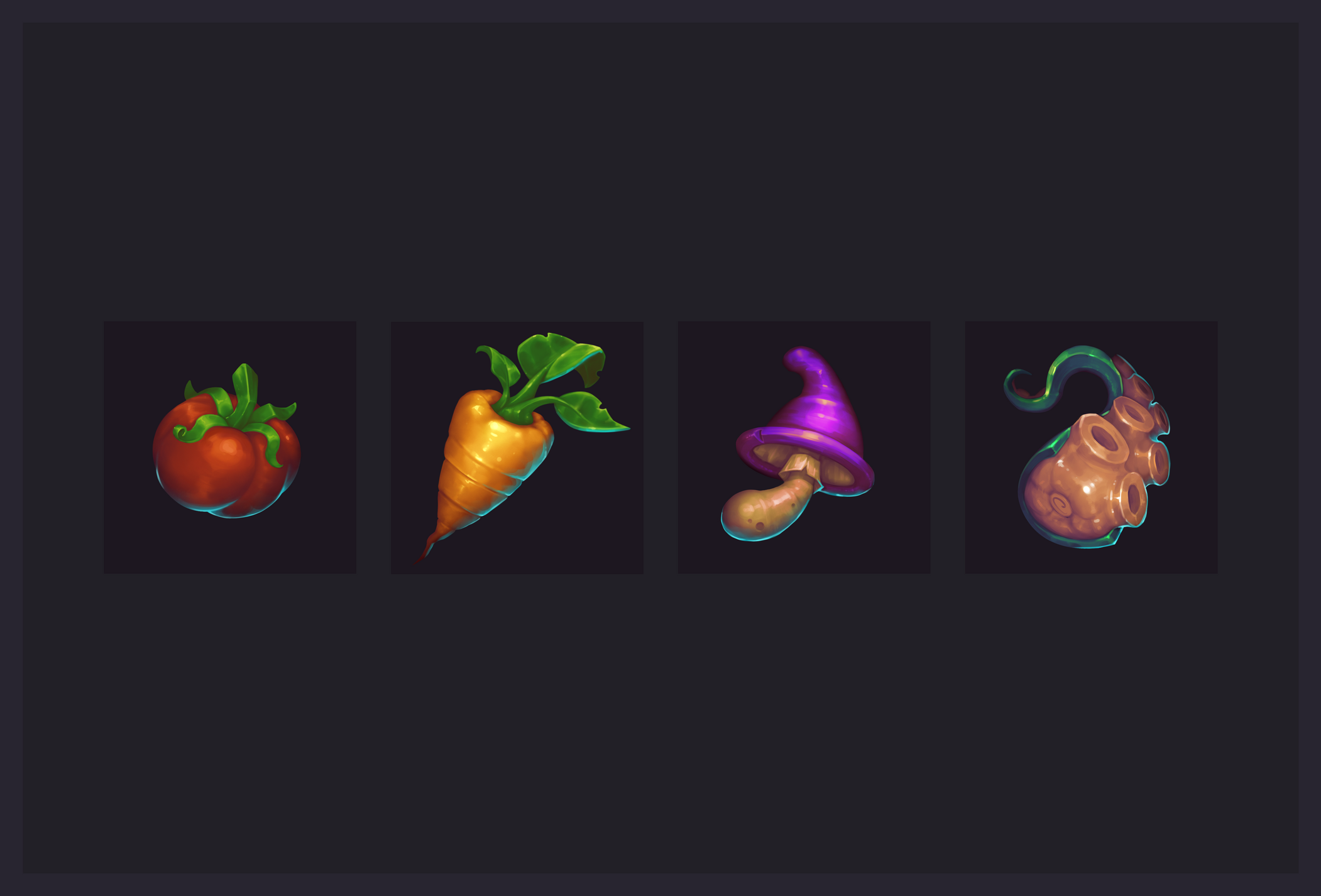
Hi all! I had a lot of fun drawing these vegetable icons, I hope you enjoy them! Hope for your support and feel free to leave feedback in the comments!
My Artstation: https://www.artstation.com/artwork/r9rJ5G
[WIP] Transport Miniverse
Hey Everyone!
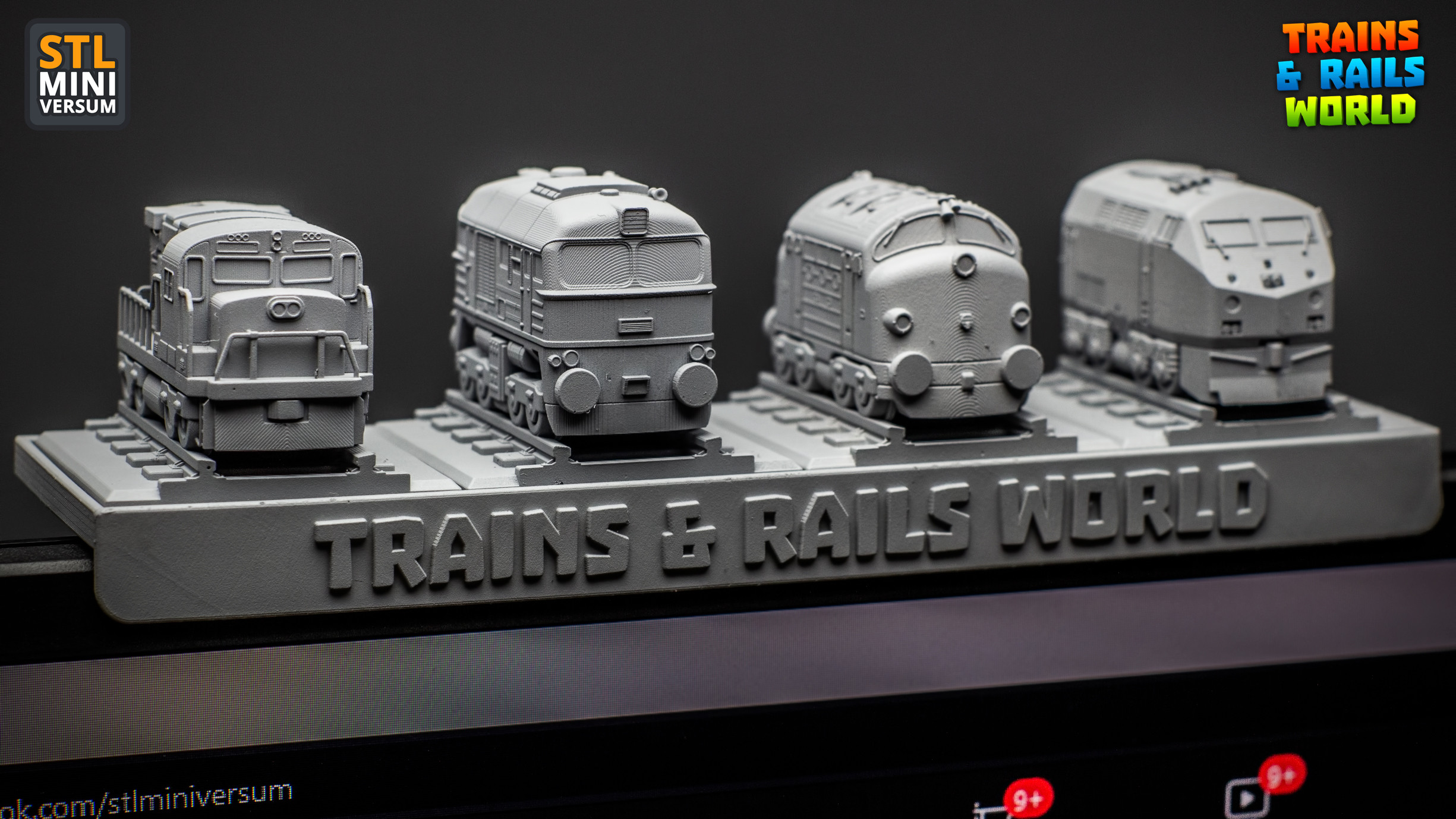
Some time ago I created a series of mini trains for 3D printing in my free time and it was a ton of fun!
You can read a bit of backstory about that here:
Or check a few more photos here:
Few weeks ago during the 2022 Game Industry Conference I had the chance to look around at the Poznań Game Arena too, and I’ve just fallen in love with all those great indie games. Some of the developers were giving away free stickers and after grabbing the first few I had the urge to collect as much as I could. :D I guess childhood memories kicked in, does anyone else remember those albums with the collectible stickers?
So these little stickers got me thinking, how cool would it be to have my train series as colorful stickers!
But unfortunately the models were for 3D printing, STL files from CAD program, messy topology, no UVs, never been painted.
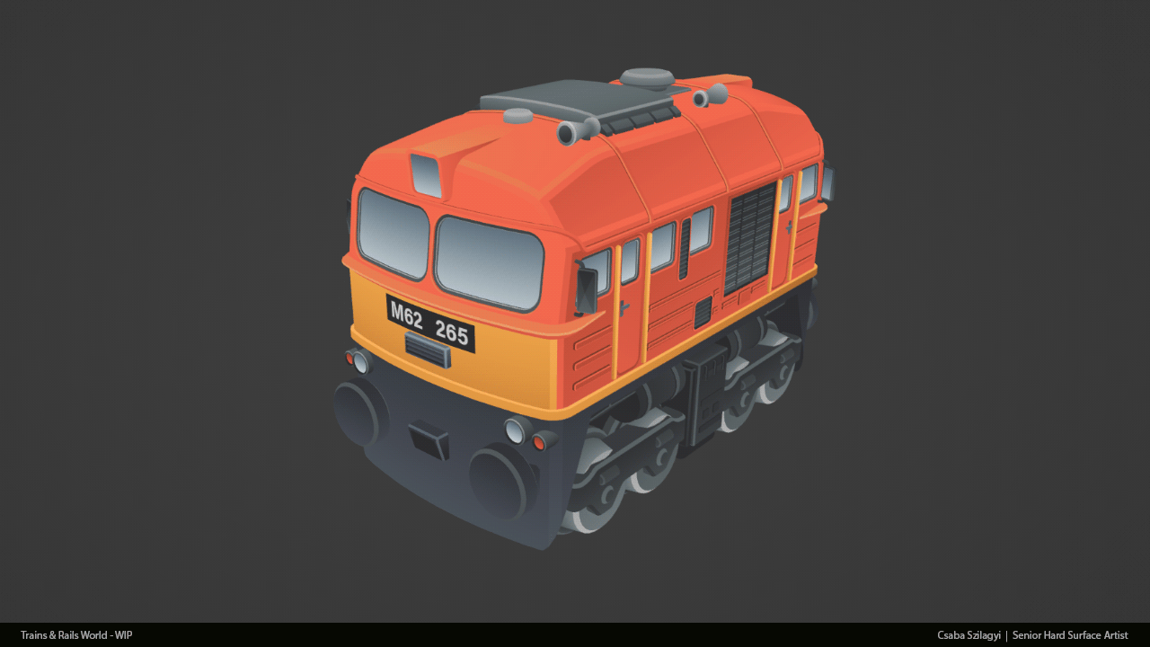
Anyway, fast forward to the boiling point when I could not resist anymore and I sat down to remodel one with UVs and textures.
This was inspired by the hungarian M62 Szergej. (These are my childhood favorites. I remember standing next to the train tracks close to my grandma’s house and watching these massive iron horses pulling 50+ fully loaded cars behind them.)
It's using this texture:

(I know, I know, so much wasted space, could be more compact. :) )
If you are a train fan, you can spot right away that the M62 locomotive has 6 axles and this one only 4.
The reason behind it is that when I came up with the first designs I made an art decision to fit all of the models to a 1x1 base plate. This limitation made designing quite challenging. I could fit all 6 axles under the train, but then the body/wheel ratio would be something that I don’t like. So… I did my best to make it look okay even if it’s wrong, focusing more on the recognizable silhouettes and main forms. And this example is not even close to what I had to sacrifice with my very long steam locomotive designs. :)
I am also not making a difference between the american and european couplers and every model is using the same, kinda cartoonish buffers. I made this decision to make the 3D printed models “compatible” with each other regardless of what locomotives and cars you put together.
I still have not ordered sticker papers to print the first test versions :) But what I did is that I exported it to Unreal Engine 5, out of curiosity, and quickly made a few more models around it.
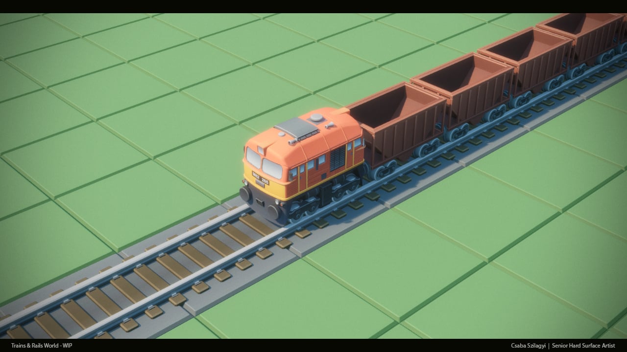
At this point I was like, what the hekk, why not… And made one more locomotive.
It’s pretty easy to model and texture them with this art style. This one took me like 7-8 hours to finish. And this is a brand new one, there is no 3D print ready base model to work with, which means some of the time was spent on checking references, proportions, forms etc.

As you can see I was fine tuning the proportions and details until the very last step, and still made a few adjustments after recording these steps.
And this is where I am now:

Still not sure where this is going...
...but 2 things I know:
- I will remodel more of my previous models to in-game models.
- I will dig deeper in Unreal Engine (spent almost the whole last decade working with RED engine, kinda forgot what is what in UE :) ) and make them move, maybe even I will try to make a mock up video about how a game would look like what I have somewhere in my head.
I’ve figured I will make posts like this to keep record of the progress. Whenever I have something to show, there will be a bigger post about it. As for now I go back and try to figure out how to make DoF in UE5. :) This is Photoshop DoF on the last shot, somehow I can not make it work on the simple CameraActor, no matter how I change the parameters…


Re: How The F*#% Do I Model This? - Reply for help with specific shapes - (Post attempt before asking)
@Neox Really appreciate the kudos.
@laeion Welcome to Polycount. Consider checking out the forum information and introduction thread.
Soft hard surface objects can be tricky to model but taking apart one of these packages or gathering references of them disassembled can provide some insight into how the paper is cut and folded to create the carton. Analyzing how these pieces fit together will make it easier to come up with a plan for modeling the shapes.
While there's a few different ways to approach this, depending on the level of accuracy required, it's generally a good idea to start by blocking out the shapes. Keeping things fairly simple during the block out makes it easier to adjust the larger forms and change the topology flow. Try to resolve any major shape or topology flow issues before adding the support loops.
If simplified fold details are acceptable then one of the easier modeling strategies would be to cut in the basic shape of the flaps and sealed seam then inset or extrude the outline to create some depth. While this approach is fairly quick and detailed enough for most background props, it won't be completely accurate. Which could be an issue if the model needs to be viewed up close.
If more complex fold details are required then it probably makes sense to model the entire seam standing up then fold it flat against the carton. This approach is a bit more involved but produces more accurate fold details. Below is an example of what this modeling process could look like.
Start by establishing the overall form then apply a mirror modifier and add a central loop cut. Select the outside edges and run a chamfer operation to create the fold line around the corners of the packing. Cut in an edge loop to define the basic shape of the flaps. Extrude this section and merge the geometry into a point. Use a bevel operation to create a square edge, that's the width of the sealed seam, along the central edge loop. Extrude the new loops upwards to create the standing seam. Add the support loops for the outer perimeter of the carton and additional loops for deforming the sides. Select the standing seam and fold it over then fold in the corners.

Adjust the position of the loops around the top and bottom of the carton. Looking at the references: the top tends to bow inwards and the bottom tends to bow outwards slightly. Loop select the edges that define the perimeter of the folded seam and corners of the box and add support loops with a bevel / chamfer operation. The folded seam on the bottom of the carton is the same as the top, only the flaps are folded inwards instead of outwards.
Though this mesh is water tight, the area under the folded seams will have some potential for overlap and could be further simplified by merging it into the underlying surface. In most cases this shouldn't be required but it is an option for any sort of edge case where the overlap causes issues.

Recap: Gather additional reference information about the folded parts of the object and use that to develop a plan for modeling the shapes. Block out the major forms and resolve the topology flow issues before adding support loops. Try to keep the basic geometry fairly simple, with relatively consistent segment spacing, then let the subdivision do most of the smoothing work around the corners of the folded flaps.
Lots of good advice on how to approach modeling the truncated sphere but when shape accuracy is important it's often beneficial to rely on mathematically consistent primitive geometry as a starting point. There's also nothing inherently wrong with using a sphere that has a central pole. It just requires a bit of adjustment to find the right number of rings and segments to get the geometry to line up with the section planes. Below is an example of what this process and resulting topology could look like.
There's also some situations where it makes more sense to use a regular sphere instead of a quad sphere or icosphere, since it's a lot easier to adjust the number of segments to line up with intersecting geometry. The remainder of partial rings can also be used as support loops. Without having to add additional geometry that would otherwise disturb the segment spacing and quality of the surface.

Quad sphere geometry tends to work well with symmetrical section planes but can run into issues when blending asymmetrical shape intersections. Both topology layouts are viable and deciding which to use really depends on what the adjacent geometry looks like.
@sacboi has a detailed post that explains a different modeling process for cutting holes in quad spheres and also covers why it's important to constrain shape changes to the transitional area between the support loops around the shape intersection.

For your latest shape question: the silhouettes on the reference sheet and the detailed side views seem to show a cut out between the two cylinders. Try using the two, parallel cylinders ahead of that area as a proportional reference then block out the larger cylinder towards the back and see how it looks with the gap that appears between the top and bottom.