Best Of
Re: Sketchbook: Tits
Hello Again!
It's been a little while so I did a couple of more pages in my sketchbook!
First I wanted to try something very simple based on a picture I took of roh and peco a little while back.
I went with a soft gouache background and lines in posca pen but I kind of miss and prefered the soft and tiner lines of my underdrawing tbh.

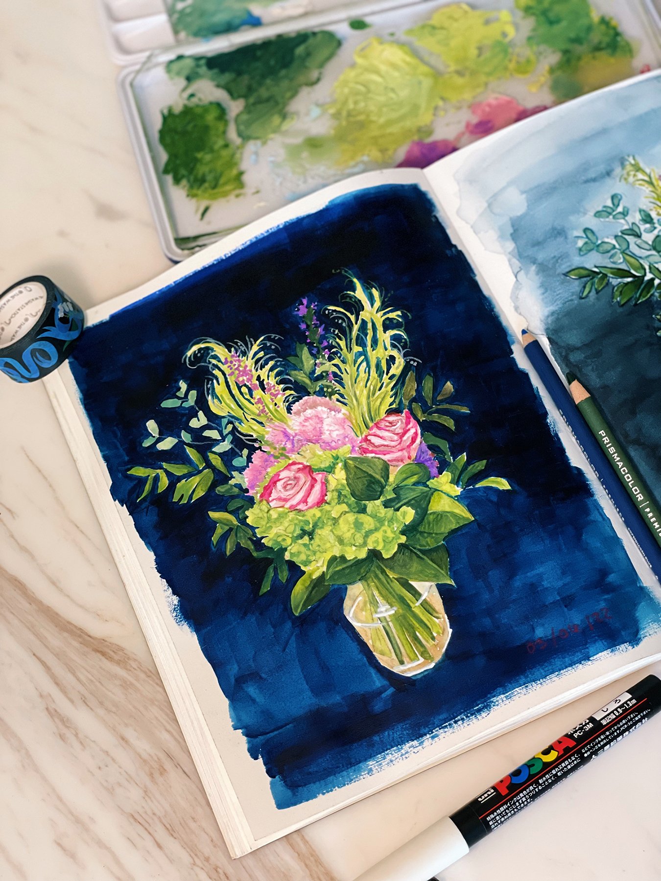
also wanted to paint the bouquet from my 3rd year anniversary, I decided to paint it in 2 medium, one in watercolor and one in gouache (trying to continue epxloring this medium a bit more)
Surprisingly I ended up not really being a fan of the watercolor one, I did ended up painting it outside and it made everything dry way too fast which posed an extra challenge. I went very ballsy with the blue background also and I kind of regretted it...
So I ended up redoing the same ballsy background on the gouache version of course. But I kind of do like it on the gouache version.
I tried to not abuse the coloring pencils on the gouache version. I did use them a bit too much on the watercolor version.

 Tits
Tits
Re: Sketchbook: Tits
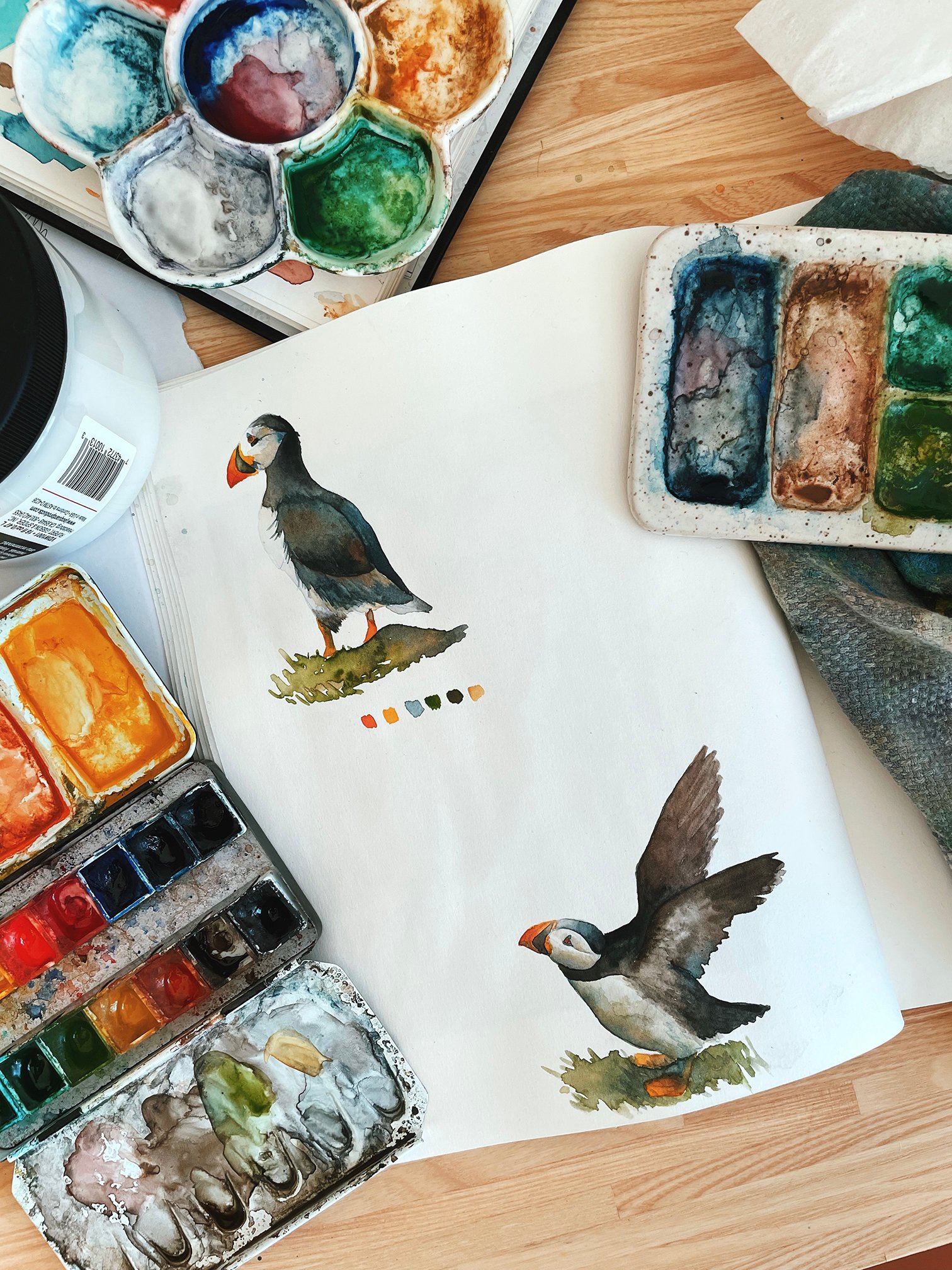
Back to my usual watercolor,
Had a lot of fun last weekend painting those little puffins based on some pictures I took of them in Iceland as well as in the faroe Islands
 Tits
Tits
Re: Sketchbook: Tits
@EricElwell Thank you so much!!
@sacboi Haha Peco has one hell of a personality so definitely could not capture all of it but I tried! Haha I don't do fridge magnets yet 😉
Been doing a lot of ''experimenting'' with new mediums and style lately.
Always been jealous of those cool artist with bunch of filled up sketchbook so I have been trying to use mine more and vary my mediums etc.
First I tried gouache for the first time and it was a lot less like watercolor than I expected and a lot harder too.
Not really happy with the result but I can say that at least I had fun and want to try gouache some more at some point.

Aside from that I had been wanting to try drawing/ painting based on many ''little isolated'' house pictures I took over the last few years traveling.
At first my intention was to do the lines in coloring pencil and then go over them with monochromatic soft watercolors.
But in the end I ended up loving the results with the lines alone and left them that way. Do want to try with watercolor another time tho, but I love the visual impact it has with the lines alone.

 Tits
Tits


Re: The Bi-Monthly Environment Art Challenge | November - December (81)
There's been some solid feedback so far so I don't have much to add at the moment. I'll continue to lurk and look forward to seeing more updates.
I appreciate that the concepts this time around are smaller scale as I don't have much free time.
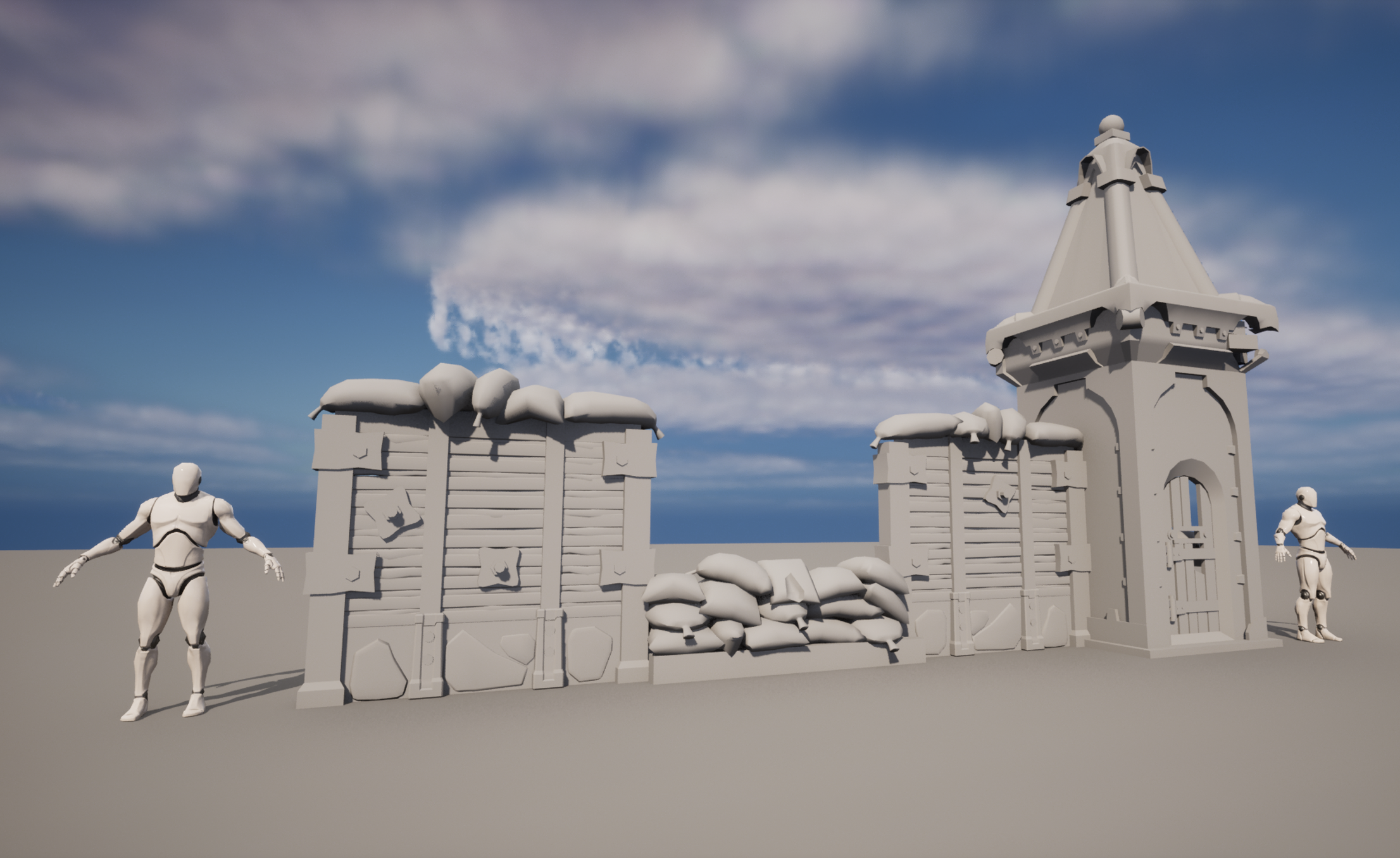
I've decided to go with the Gears 5 artwork. I like that there are a lot of interesting shapes and materials in a small piece. I've been working on pre-production and getting a block-out finished to iron out all the small shapes and the scale of everything. I've been looking at it for too long so it's time to get some other eyes on it, I appreciate any feedback.


Re: ZBRUSH - All new updates to require Maxon subscription
Also, another word of caution : if one is a user of an older version of Zbrush (for instance because of dependencies on brushes and plugins, or even just as a matter of preference), Maxon support will not provide authorization for a reinstall and will force one to upgrade to the last non-sub version, which is 2022.05. So for instance, the installation file for 4r7p3 is not available anymore, and the authorization server doesn't run anymore either.
In my opinion this is pretty much the beginning of the end of the Zbrush era, especially with many new artists going straight to Blender for sculpting.
 pior
pior
Re: What Are You Working On? (3D) 2022
3D stylized cassette player which I designed and created. I also added a small rig and animation for its door.
More pictures and 3d view from sketchfab : https://www.artstation.com/artwork/Ze4g3R
All pictures and the clip are rendered in EEVEE
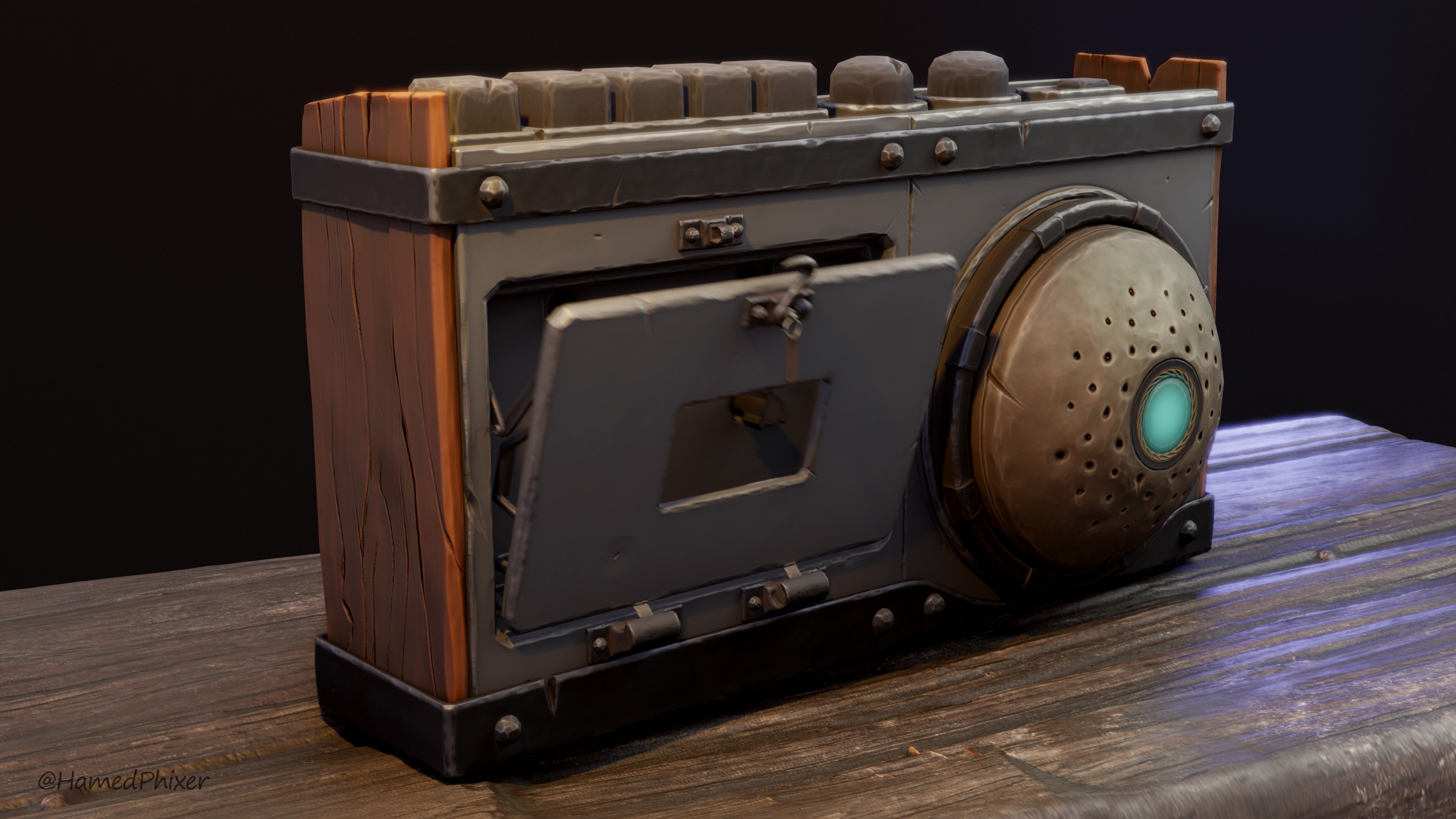
PS: Working on this helped me release my stress in some level because of the critical situation in my country Iran which the murdering of innocent people and protesters is happening as we speak for basic human rights. Our main motto is Women, Life, Liberty.
 HamedPhixer


Re: [WIP] Horizon FW prop: paper cutter
I've been reworking this piece a bit based on some other feedbacks I've received!

Been working on the rendering in unreal and tweaked my roughness and metallic values a bit to have less harsh variations in the metal. I also lighten the metal albedo up a bit and homogenized the values between the different metal parts so it doesn't seem so different. I also cleaned up my topology a bit.
I feel like this is in a good enough place to let it off for a bit now! Here's my final artstation post for the showcase video, mesh and high rez screenshots: https://www.artstation.com/artwork/xYnWG2
 simonBreumier
Re: What Are You Working On? (3D) 2022
Finished this little environment inspired by Sephiroth Art and old school isometric RPGs.
 qdpat
qdpat