The BRAWL² Tournament Challenge has been announced!
It starts May 12, and ends Sept 12. Let's see what you got!
https://polycount.com/discussion/237047/the-brawl²-tournament
It starts May 12, and ends Sept 12. Let's see what you got!
https://polycount.com/discussion/237047/the-brawl²-tournament
Best Of
Re: Greentooth Sightings in Videogames

Edit:
While stylized stuff may not necessarily be my cup of tea per se but anyway all the same, liked how the artist finished it off ")
 sacboi
1 ·


Re: [WIP] The Staircase - Environment
@pixelpatron @sacboi - Thank you for encouragement, much appreciated 
Continued to work on the materials.


(Made the wood lath in Zbrush and then exported the heightmap to SD and finish the rest of it there.)


I've been learning Unreal material nodes for the past month. So far, I've implemented vertex painting, ability to change colour tint, roughness / normal intensity, RGB masks, parallax occlusion ect.


Now that the hardest part is done and the master material functionality is somewhat working, next I will finish the remaining assets, polish the scene, make decals, rework the lighting.
Continued to work on the materials.
(Made the wood lath in Zbrush and then exported the heightmap to SD and finish the rest of it there.)
I've been learning Unreal material nodes for the past month. So far, I've implemented vertex painting, ability to change colour tint, roughness / normal intensity, RGB masks, parallax occlusion ect.
Now that the hardest part is done and the master material functionality is somewhat working, next I will finish the remaining assets, polish the scene, make decals, rework the lighting.
1 ·
Re: How The F*#% Do I Model This? - Reply for help with specific shapes - (Post attempt before asking)
@okidoki Thanks! Really appreciate your concise explanations and feedback. It's always nice to see the community work together like this.
@stray There's definitely some ambiguous shape transitions that are a challenge. Really like how you interpreted those iffy spots on the concept and translated it into an asymmetric front and back where the spiral ends near the pommel. Keep up the good work!

@5rettski Looks like you have the basic idea down. It just needs some refinement.
Here's the order of operations used in the previous example: Create the basic profile for one of the flutes and copy it so there's four of them perpendicular to each other. Add a screw modifier and set it to something like 32 steps and adjust the distance until the angle of the flutes lines up with what's in the concept image. Increase the iterations to two and adjust the position of the mesh so the whole spiral extends well beyond what's visible in the concept.
Use diagonal slices across the ends of the spiraled flutes then remove all of the left over geometry. Fill in the ends of the channels by connecting the edges and faces until there's a clear loop path around the base of the shape transition. (Highlighted edge in the middle of the image below.) Extrude this edge loop downwards and flatten it to create the cylindrical part of the grip.

Some of the shapes in the concept are ambiguous because they connect to each other in magical ways that only really work in 2D. So how and where the spiraled flutes end on the other side of the grip is open to interpretation. Based on what's shown in the concept: there's a couple visual clues that suggest the ends of the flutes do not extend beyond the center line of the cylinder. If they did, they'd be visible from the front and since they aren't visible, well there's no other place for them to go.
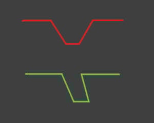
How that's resolved is largely a matter of taste. It's possible to simply slice them all off vertically along the axial plane but that's a bit plain and unrefined looking. Slicing across them diagonally means the ends will be staggered and that creates a V shape that provides some visual contrast to the spiral. It's also possible to reduce the depth of the channel near the ends (not shown) and that way the flutes kind of ease in / out and aren't so abrupt.
From a purely practical point of view, a grip like this would be very uncomfortable and the flutes should probably be a lot shallower so there's more contact area but that's not in the concept so that gets into the whole topic of whether or not it's worth redesigning things a bit... To make it both more realistic and easier to model.

2 ·
Re: Greentooth Sightings in Videogames
Found one!
Loud and proud.
Fl4k Boarderlands 3
Main menu.

Loud and proud.
Fl4k Boarderlands 3
Main menu.
 kanga
kanga
2 ·
Re: How The F*#% Do I Model This? - Reply for help with specific shapes - (Post attempt before asking)
This is so helpful, just two questions.
And,
Is this how you have it set up in blender? One raised more than the other? Or are they all level?
By this, I would use the knife or multi cut tool correct?Use diagonal slices across the ends of the spiraled flutes then remove all of the left over geometry.
And,
Is this how you have it set up in blender? One raised more than the other? Or are they all level?
1 ·
Re: Anime stylized character creations
Downloads for the ZZZ models are available from the official website and can be imported in Blender using the mmd_tools addon.
https://www.bilibili.com/blackboard/activity-vl9IMaaeyZ.html


So assuming that you already have a design sheet for the character you want to model, with a little bit of studying of the original models you'll be able to match their execution style. Unlike Arcsys style models, Genshin Impact and ZZZ characters are actually fairly simple as they don't rely on any advanced UV trickery, just regular texturing.
https://www.bilibili.com/blackboard/activity-vl9IMaaeyZ.html
So assuming that you already have a design sheet for the character you want to model, with a little bit of studying of the original models you'll be able to match their execution style. Unlike Arcsys style models, Genshin Impact and ZZZ characters are actually fairly simple as they don't rely on any advanced UV trickery, just regular texturing.
 pior
pior
2 ·
Re: What made you feel good today?
Just vegging while looking at low poly art by Mr Bolton:

 sacboi
1 ·
Re: Basic topology exercises Giz
The conclusion I came to is that you ideally want to use the same sort of tools the original designer used because the tools you use affect the things you design quite significantly
eg. if you're modelling consumer electronics or cars designed in the 90s you likely want to be using a NURBs based modelling toolset.
More recent stuff is more likely to translate to subdivision modelling or modern CSG based CAD
if it's a casting - use booleans and zbrush
eg. if you're modelling consumer electronics or cars designed in the 90s you likely want to be using a NURBs based modelling toolset.
More recent stuff is more likely to translate to subdivision modelling or modern CSG based CAD
if it's a casting - use booleans and zbrush
1 ·
Re: How The F*#% Do I Model This? - Reply for help with specific shapes - (Post attempt before asking)
Well.. you just used two points.. for the top/head of the thread and so didn't rotate/skewed the inner part and your modeling afterwards simple wasn't following the "skewing/rotaing" of the thread.. so you made yourself extra work by doing this manually when you could this in the first place more parametrically with the screw modifier.
So: you was almost there.

Ohh.. an dwhat i see only just now .. the profile is more like so:
So: you was almost there.
Ohh.. an dwhat i see only just now
 okidoki
2 ·