Best Of
Re: [GODOT4] [Released] 3D Playable Winter Game Environment Demo made in Godot
UPDATE #03
- updated soroundings
- blockout seems to be done so next will be shader setup for texturing


- updated soroundings
- blockout seems to be done so next will be shader setup for texturing

 jedenjenda23
3 ·
Re: [GODOT4] [Released] 3D Playable Winter Game Environment Demo made in Godot
UPDATE #02
- continuing with new shapes since the environment was kind of boring.
- blocking out some rough colors as well to test the overall mood
- temp lighting


- continuing with new shapes since the environment was kind of boring.
- blocking out some rough colors as well to test the overall mood
- temp lighting
jedenjenda23
3 ·
Re: [GODOT4] [Released] 3D Playable Winter Game Environment Demo made in Godot
UPDATE #01
The environment is inspire by 18th century painting of Dutch people skating on frozen canals. I will try to put something lighearted into environment story as well. As you can see the main focus point of this scene is a town bridge entrance gate. The town it self will be low fidelity vista asset but the rest of the environment will be traversable. I also put a lonely cabin at the edge of the forrest for players to explore.
There are still some improvements for the terrain, layout and reference gathering to be done, but the overall idea is roughly there.
- blockout done
- basic reference list done
- started working on asset list (currently in progress)
- exported blockout into Godot to test collisions, setup and to establis pipeline (using .Gltf format)
- got FPS controller working (reused one of the templates for now)
jedenjenda23
3 ·
Re: Clayform Sculpting App
Noth said:@Vexod14 that's part of why I want to build something, I wanted to go back to Zbrush and didn't have a license, I never bought a persistent one, I just had them from work but that changed eventually. I couldn't go sculpt for then fun. I couldn't justify the subscription for an occasional use, since I wasn't using it for work either. I really want a low cost option in the space. I do want to support something like retopo, but again yeah I think if you could just edit the base mesh model then you wouldn't really even need retopo.. you know? skip retopo but offer UVs then export base + HP for baking in Marmo.
@Neox still happy to hear your thoughts on the sculpting there and going back and forth from modelling/sculpting there. I haven't got into that, it's been on my todo list for ages.. I've read plenty about Blenders geo cap and lag in higher targets since it's all on the CPU -- have you ran into that yet? I imagine it's more of a, switch to modelling your low poly to sort things out, switch back to sculpting after once you've lowered things -- not sure if it works like that but seems like a good bet for a software that has it all.
Also I set this up to feel like ZBrush so alt is masking, ctrl+alt out of the mesh is discard mask, I just need to setup invert mask. Smooth is shift (is that what you mean?) I build mask and smooth to be their own brushes too, but they have special alternate hotkeys that mirror ZBrush so the muscle memory for some is just there.
it might be just my lack of knowledge but no matter which smooth brush i used, extension/addon or built in the first pic is the best i could manage inside blender, also using edge flow, relax and other per vert/edge/face methods. But zbrush's alt smooth is just far superior as shown in the second image


3 ·
Re: The Bi-Monthly Environment Art Challenge | May - June (102)
Hey there, don't know if it's okay to post still, but I wanted to show final renders since I've managed one last effort to finish the thing 
Godot - added a custom "specular" shader to have stylized highlights. Debatable if it's payed off, but I wanted to try. For science! Also, now I know just a little bit more about lighting, so there's that.
Though I couldn't replicate eye refraction exactly, because I had trouble converting texture data from tangent space, so it looks off. Still, had to stop somewhere:

Blender - same materials, but it's basically an emission shader with a single "fake" light object to simulate lighting. Refraction works as expected in this one:

It's been fun")
Godot - added a custom "specular" shader to have stylized highlights. Debatable if it's payed off, but I wanted to try. For science! Also, now I know just a little bit more about lighting, so there's that.
Though I couldn't replicate eye refraction exactly, because I had trouble converting texture data from tangent space, so it looks off. Still, had to stop somewhere:
Blender - same materials, but it's basically an emission shader with a single "fake" light object to simulate lighting. Refraction works as expected in this one:
It's been fun
 stray
stray
4 ·
The Bi-Monthly Environment Art Challenge | July - August (103)
Welcome everyone to the 103rd Bi-Monthly Environment Art Challenge for the months of July and August!
This challenge is a way for real-time 3D artists to test their skills and create a piece of work based on concepts provided. It's open to those of all skill levels and we do our best to provide meaningful feedback along the way so everyone can come away from the challenge with actionable points on which they can improve their craft!
- ENVIRONMENTS -
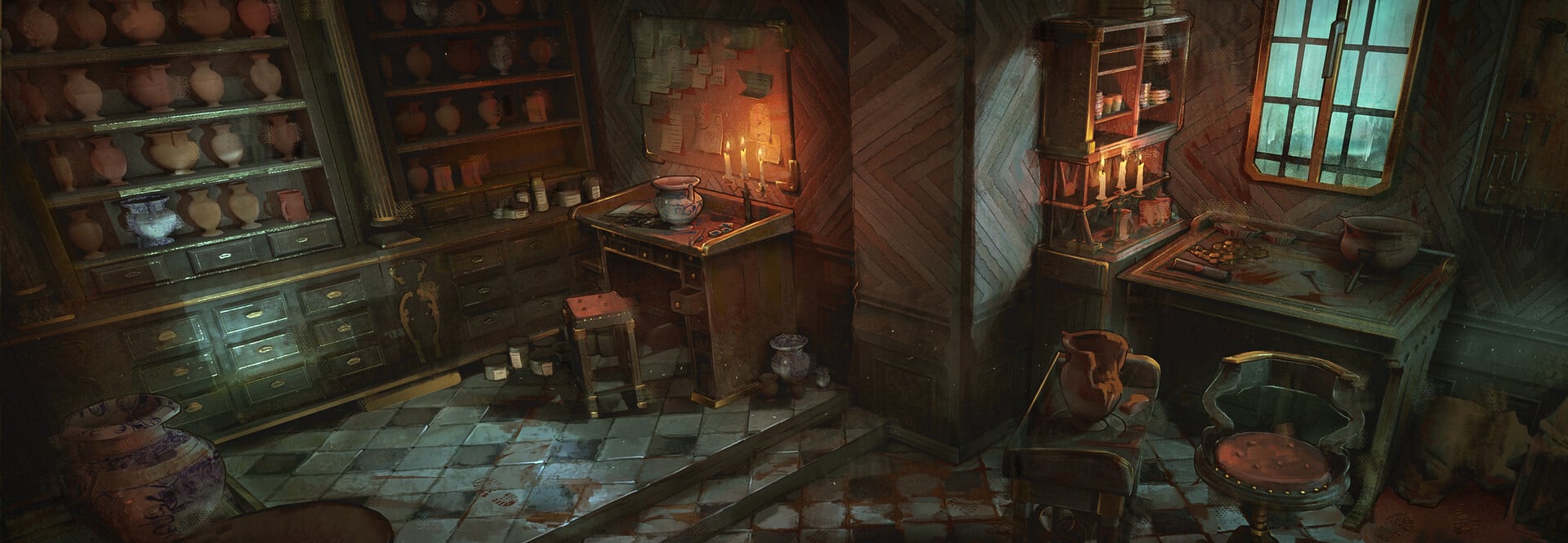
HARD SURFACE ENVIRONMENT:
Interior design - Pottery - part 1 by Mathéo Argence
https://www.artstation.com/artwork/x34Bgr
https://www.artstation.com/artwork/x34Bgr
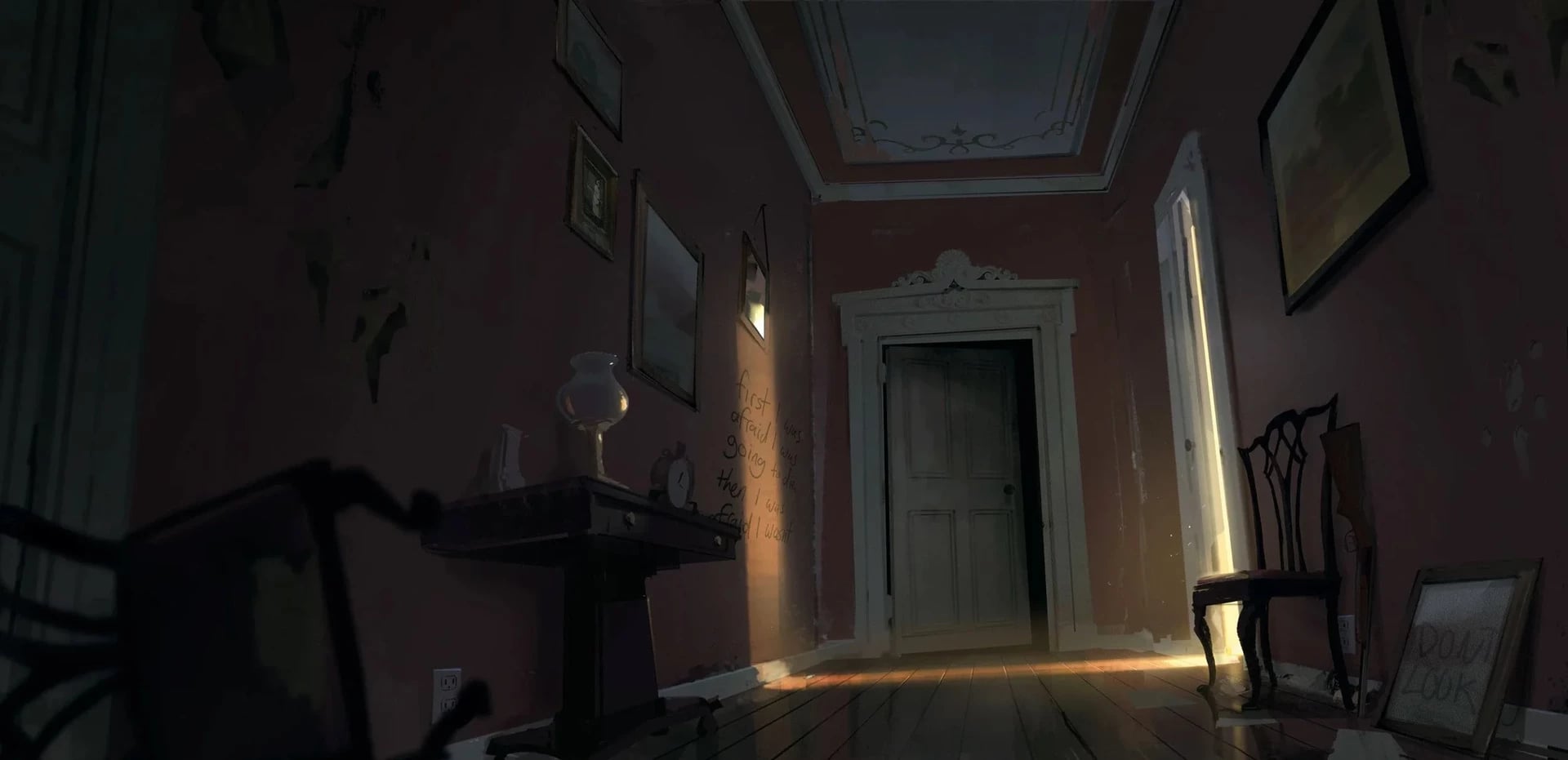
STYLIZED ENVIRONMENT:
TWD: Saints and Sinners Environments by Dylan Scher
https://www.artstation.com/artwork/4NW981
https://www.artstation.com/artwork/4NW981
- PROPS -
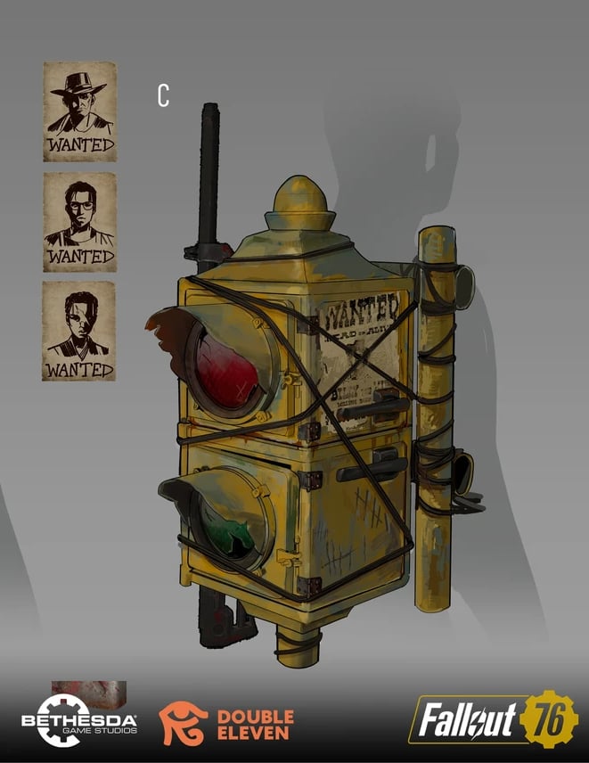
HARD SURFACE PROP:
Fallout76 - Furniture/Backpacks by Laila Godwin
https://www.artstation.com/artwork/nJRoJ1
https://www.artstation.com/artwork/nJRoJ1
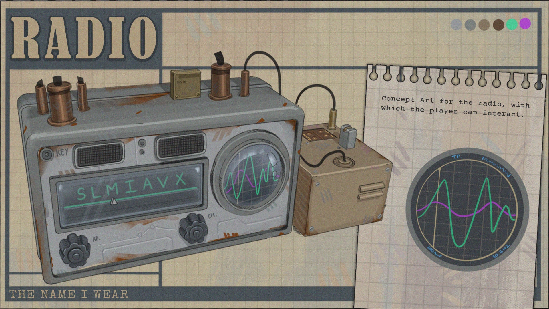
STYLIZED PROP:
THE NAME I WEAR - Concepts by Sacha Bour
https://www.artstation.com/artwork/qJ41oL
https://www.artstation.com/artwork/qJ41oL
- RULES -
Please read all the rules before starting:
- Try to post at least one critique for every post that you make. This will make for a better learning environment and help us all grow as artists.
- Try your best to finish as much as you can in the time frame provided, but remember even if you don't finish by the end of the challenge we encourage you to keep pushing and finish your piece!
- Post what you are working on in this thread so that way it's a more centralized place for advice and critique. Please avoid creating a new thread as we don't want to spam out the forums.
- It is recommended to use a game engine to present your work. Unreal Engine, Unity, and Godot are very common engines that can be used but feel free to use any alternatives that you want.
- 3D Viewers (Sketchfab, Marmoset Viewer, etc) are welcome, but please note that their contents can be stolen by those who know how. Please ensure you're comfortable with this potential before using one.
- Feel free to change up your chosen concept a bit if you want! Interpret these concepts to your liking, especially if your aim is to add storytelling elements.
- If you finish your project and decide to post it to something like Artstation, make sure you give credit to the concept artist in the form of a link to their profile. Additionally, it is recommended to ask a concept artist for their permission to post a 3D piece based on their work before doing so.
- RECOMMENDATIONS -
- When you are just starting out making a scene, it can seem complicated or imposing. Take your time planning and blocking out, it will set you up for success later on.
- Think about how you can re-use assets, re-use textures, break it down as simple as possible and plan it out. A lot of people will break it down in their own way when they start out their challenge. Gather some reference images as well for different parts of the scene, don't be afraid to make it your own.
- We strongly encourage you to go and look at other games and see how they make their assets as well as get concept art to give it your own feel.
- The goal is to learn and grow both artistically and in your ability to both give and receive critique, but don't stress about it and remember to have fun!
 Pinkfox
3 ·
Re: [Finished] Weapon Art - McMillan CS5 (Sniper)
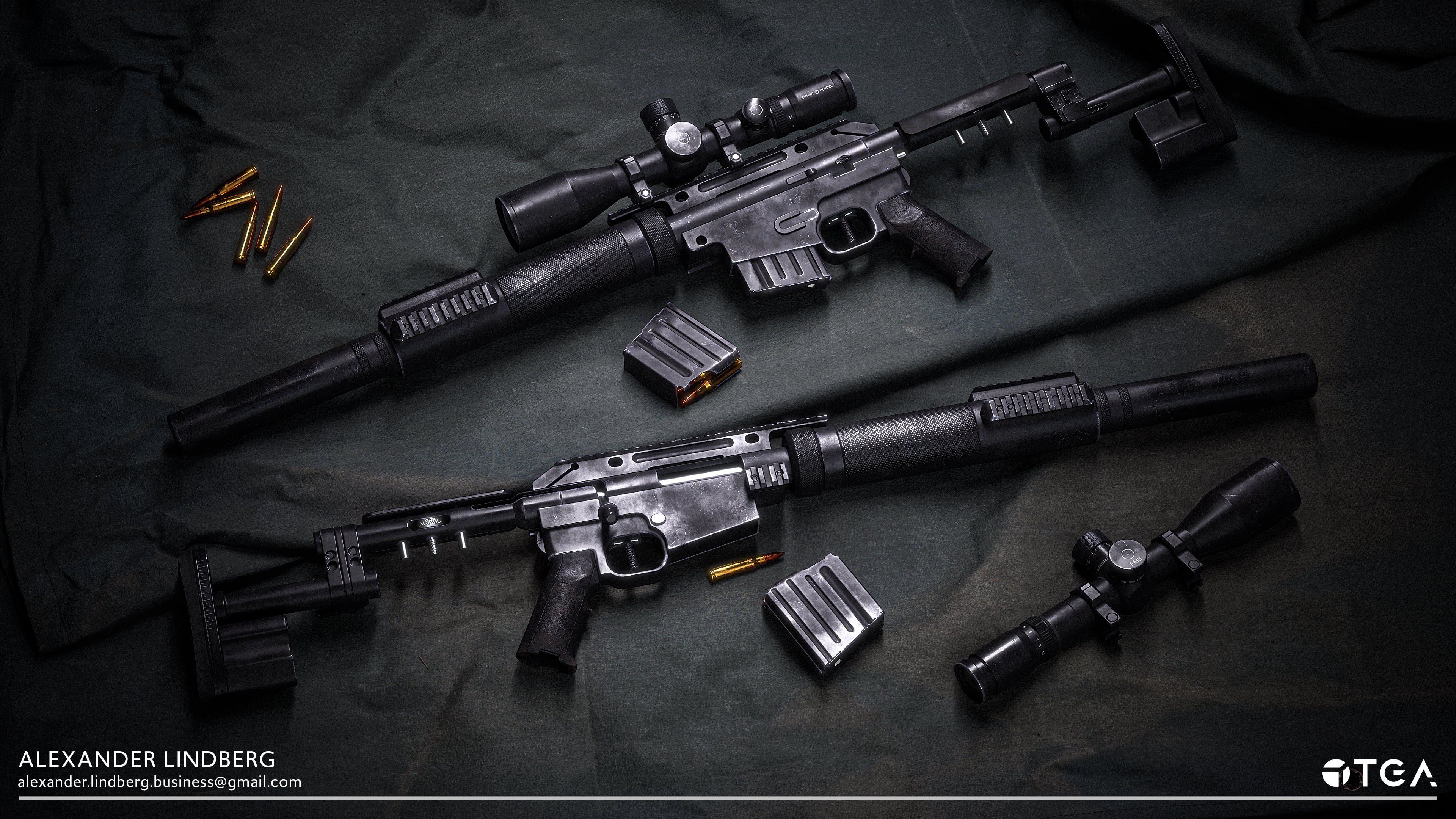
And the project is finished! Feel overall happier with the end result and can now let the project go. You can find the link for the post with the rest of the renders here: https://www.artstation.com/artwork/zxbwDD


4 ·
Re: [Finished] Weapon Art - McMillan CS5 (Sniper)
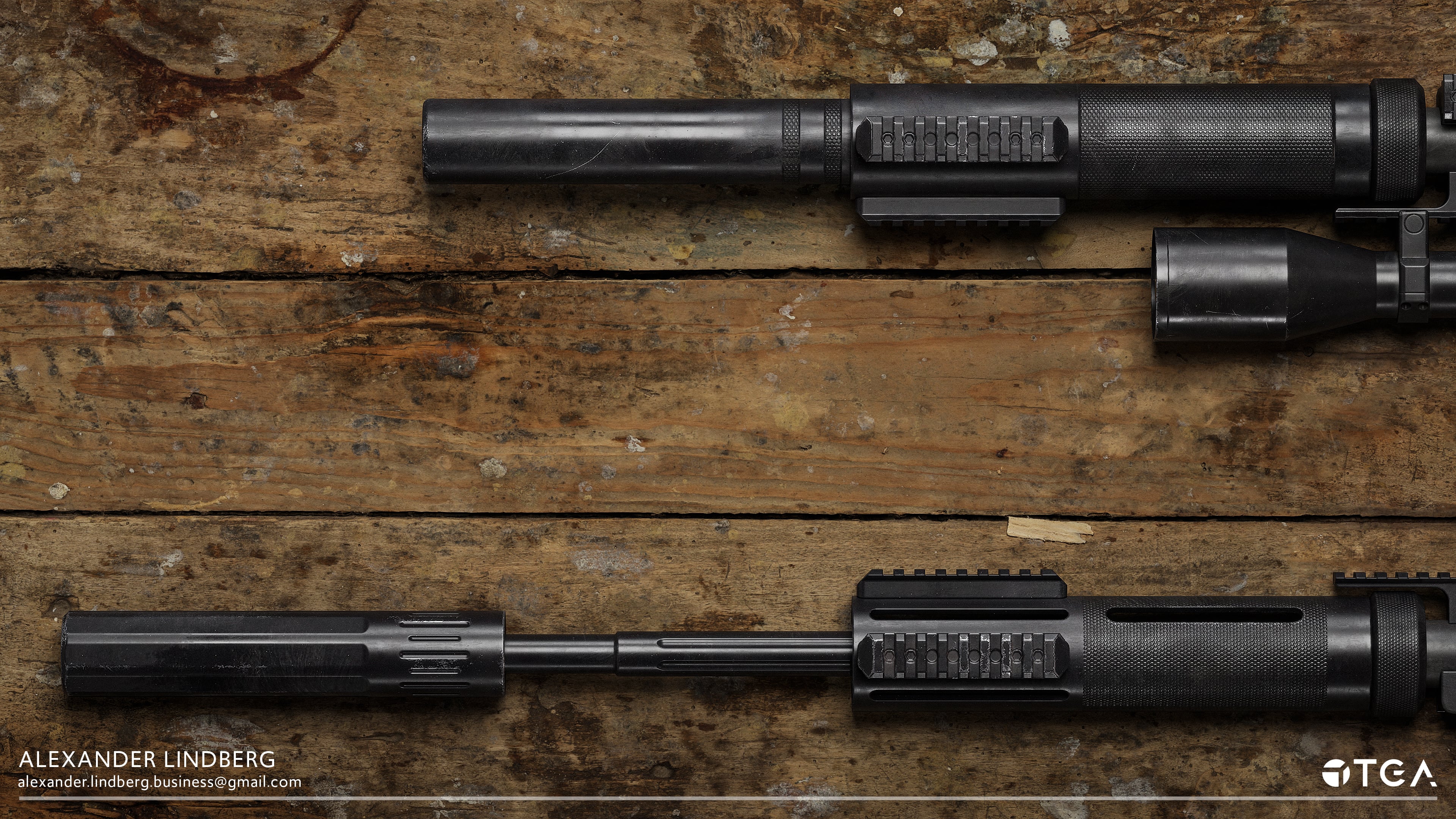
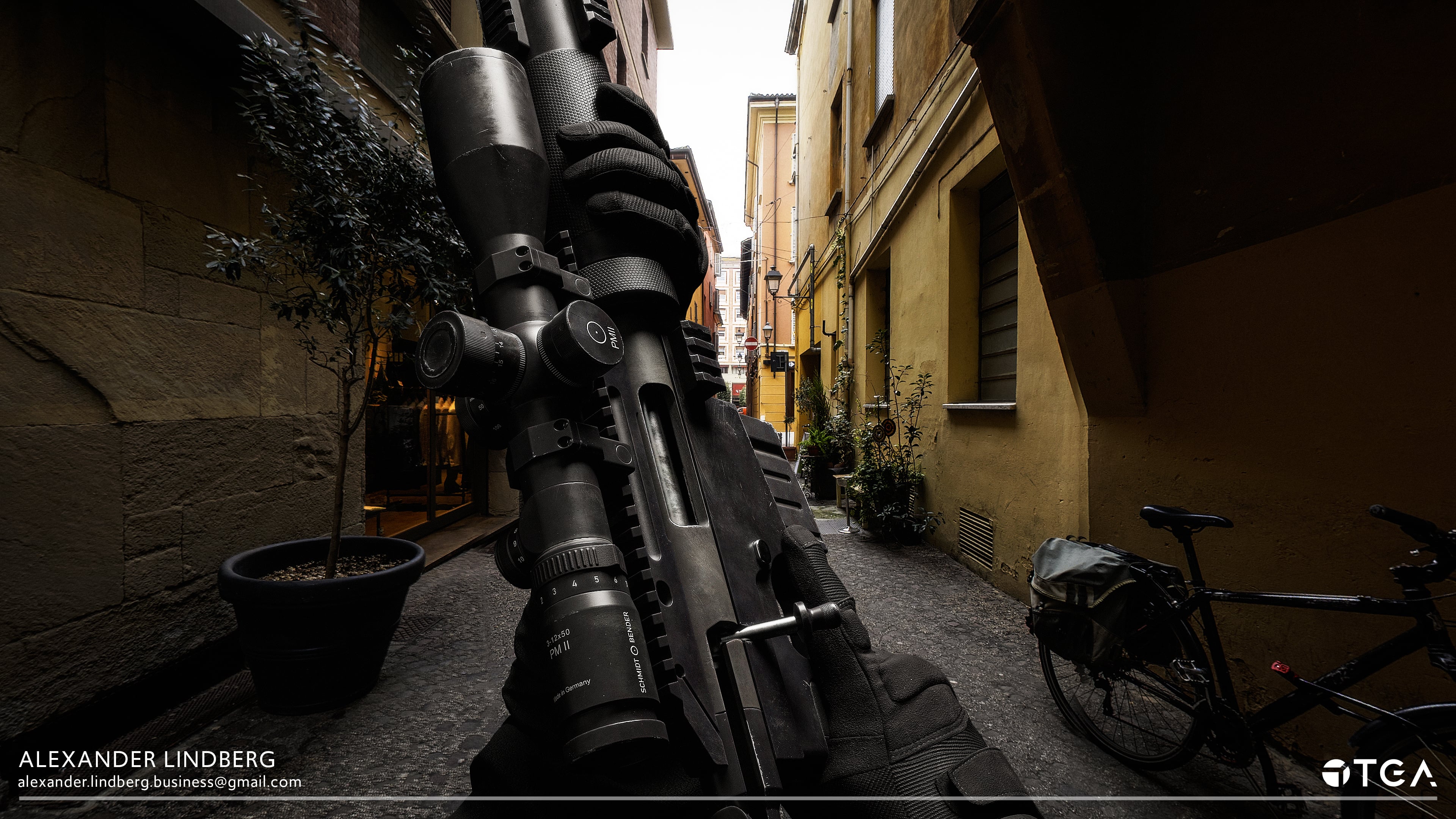
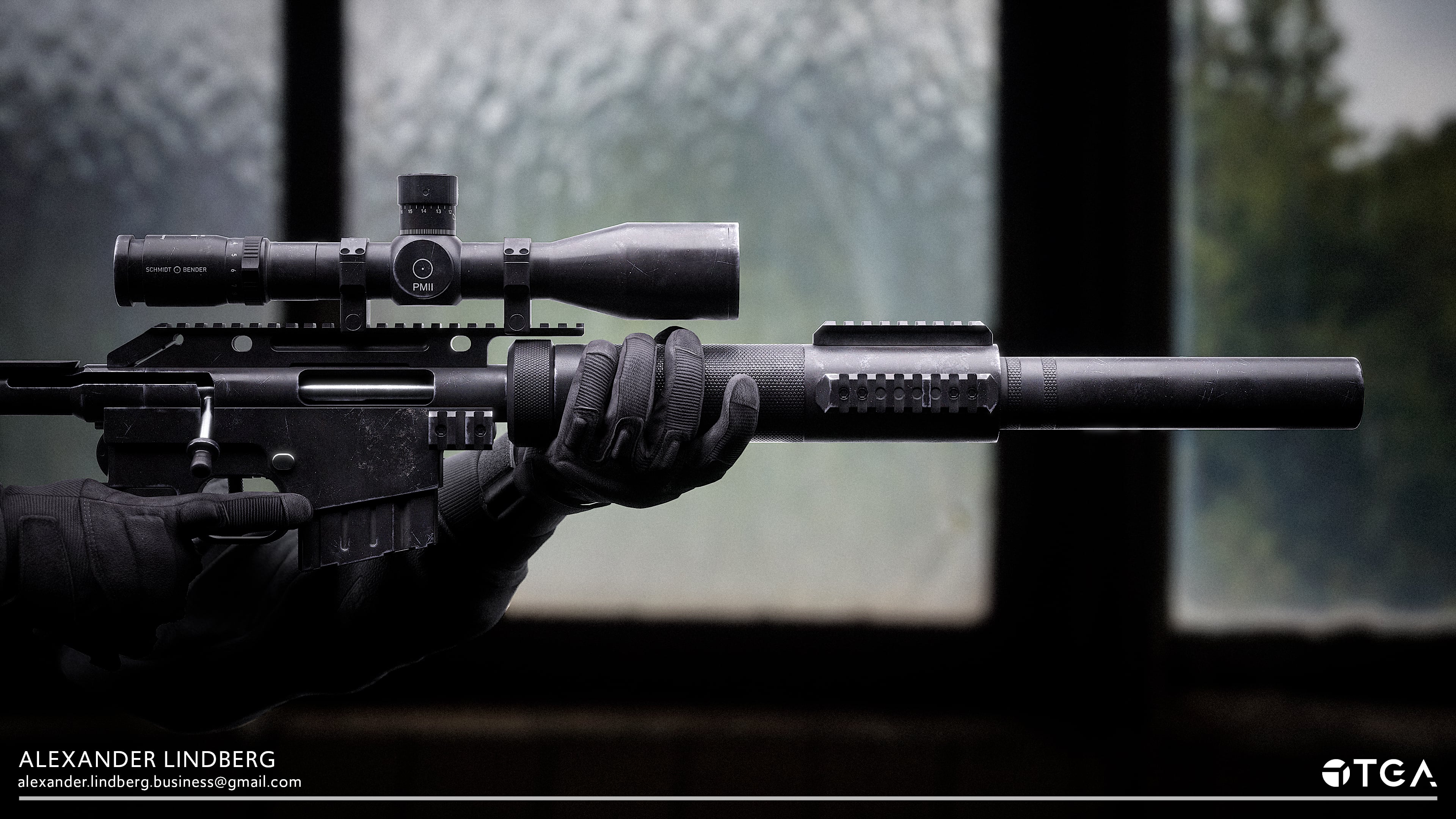
Hey y'all, I have finally published my work but still feel like it could use some more iterations before I let it go. I'll post some images below:
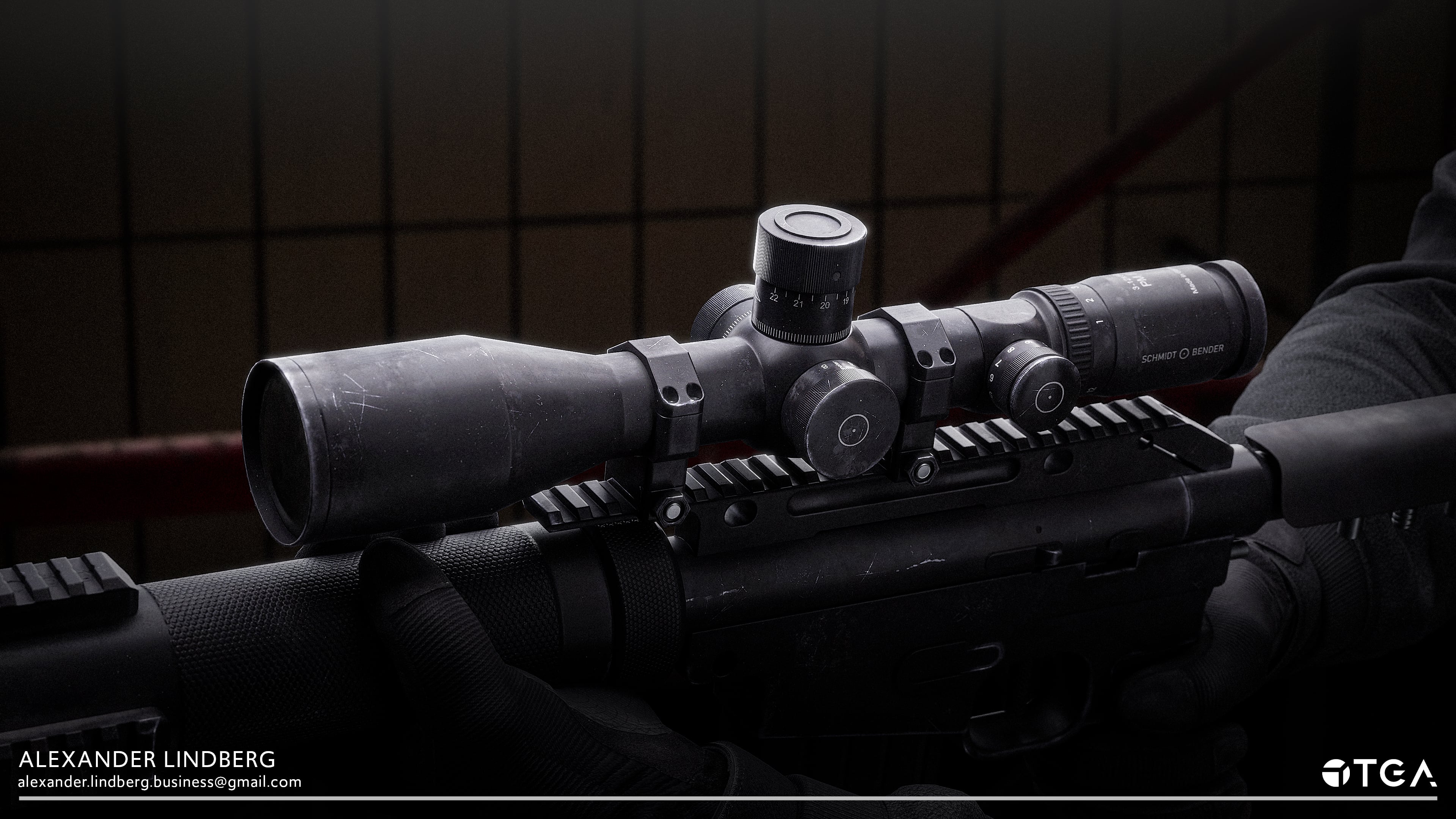
In this project, I also created
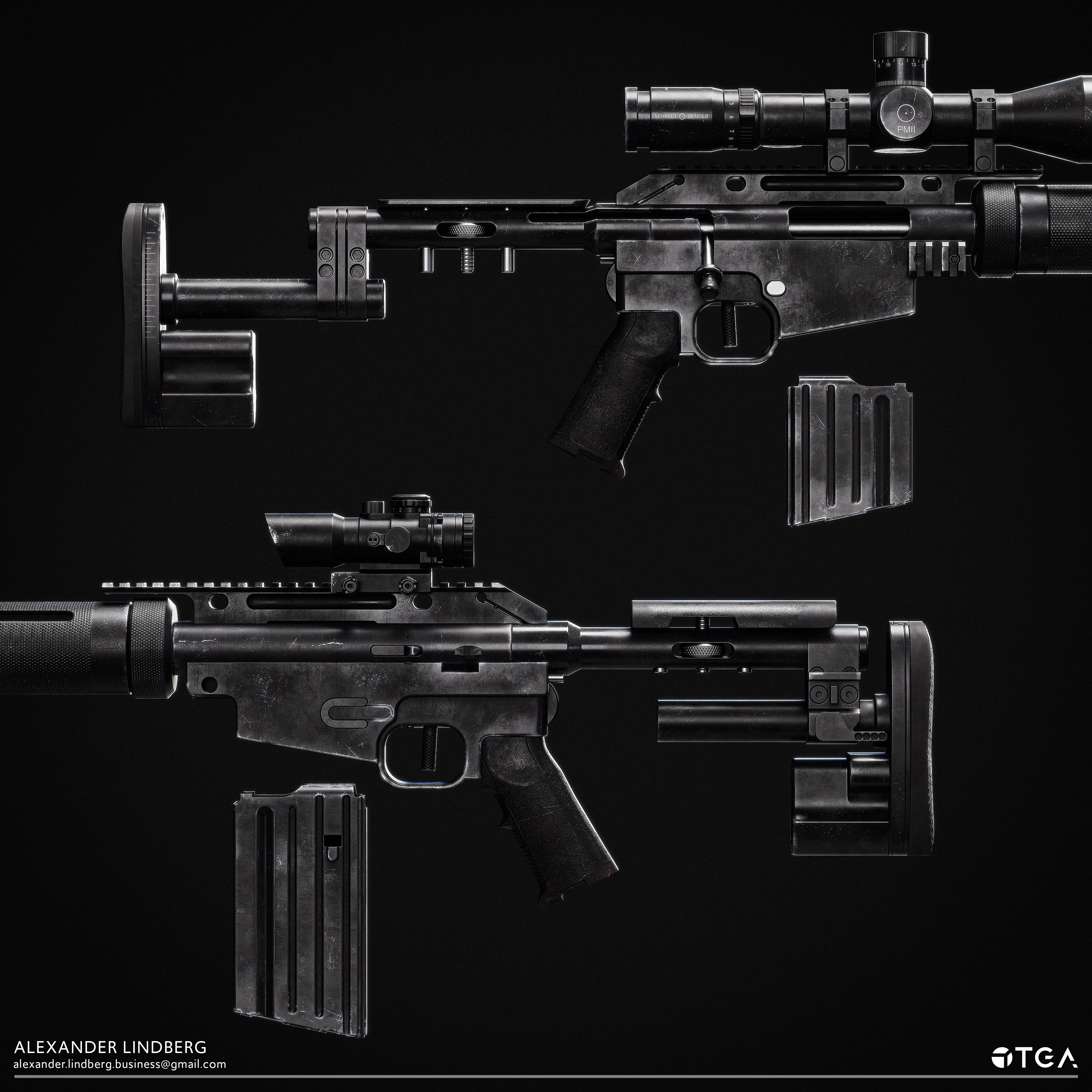
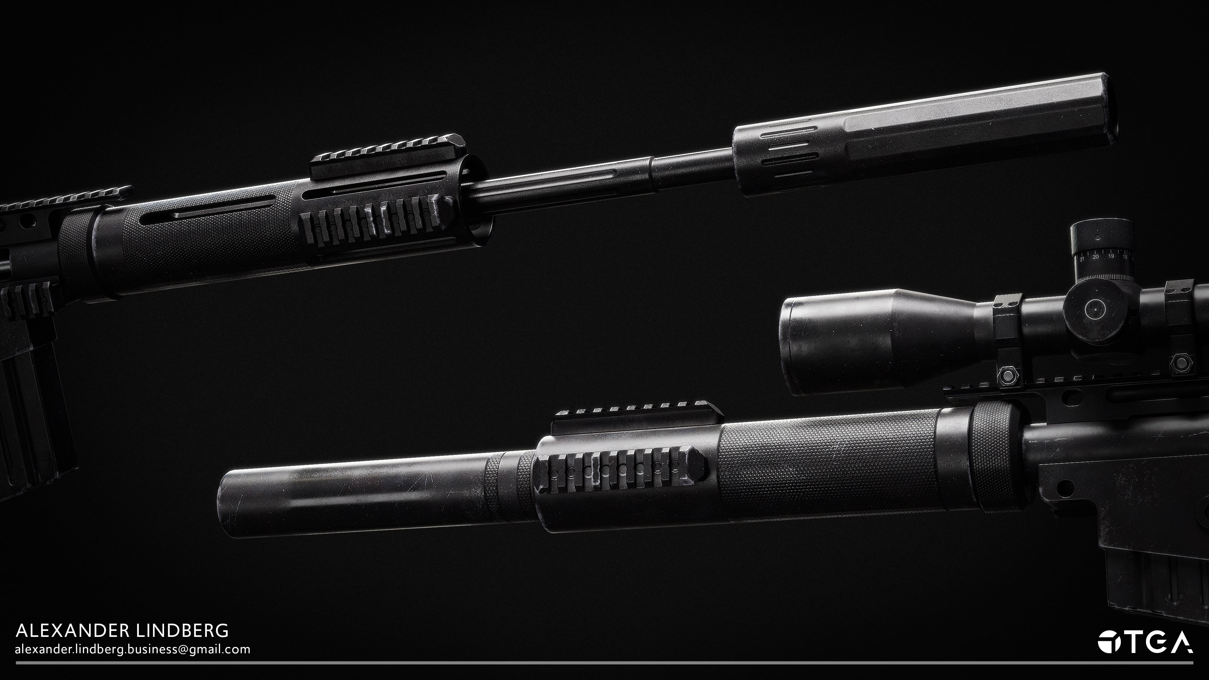
With artwork lended to me by a friend, I also made an alternative skin:
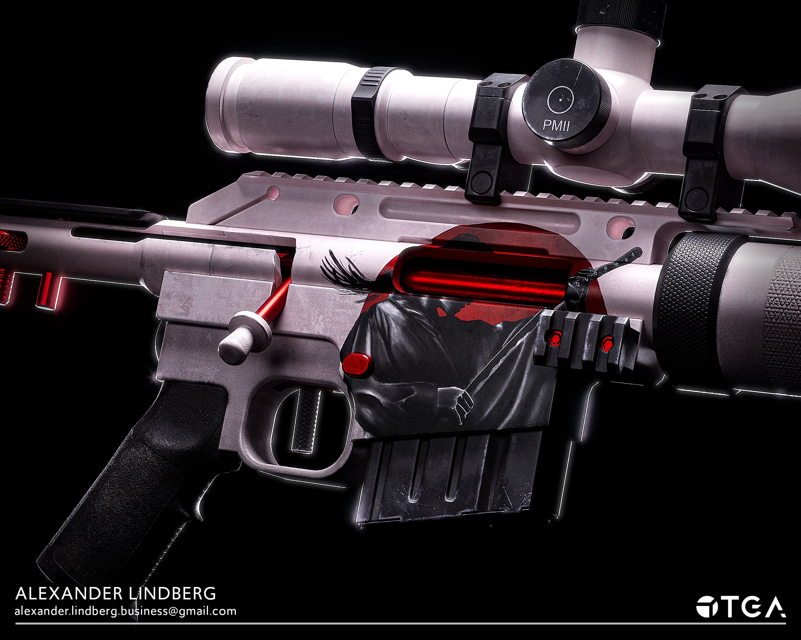
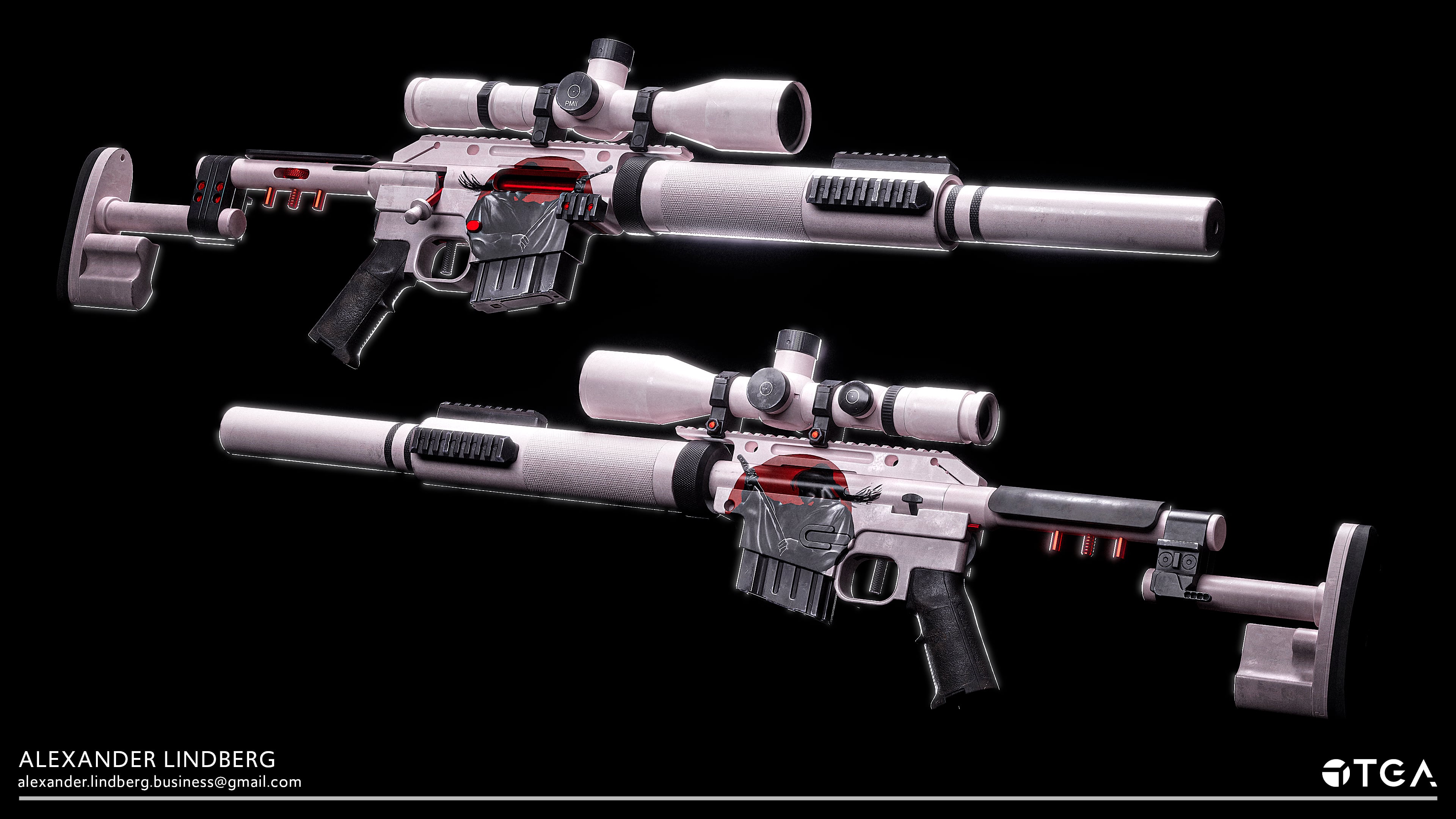
The plan is to gather feedback and re-render all of the shots in marmoset this time, not Unreal Engine.
You can find the full post with breakdowns in my ArtStation: https://www.artstation.com/alexanderlindberg
In this project, I also created
With artwork lended to me by a friend, I also made an alternative skin:
The plan is to gather feedback and re-render all of the shots in marmoset this time, not Unreal Engine.
You can find the full post with breakdowns in my ArtStation: https://www.artstation.com/alexanderlindberg
3 ·
[Finished] Weapon Art - McMillan CS5 (Sniper)
The McMillan CS5 is a weapon I have been working on and off for while in my spare time and I wanted to start posting my progress so far.

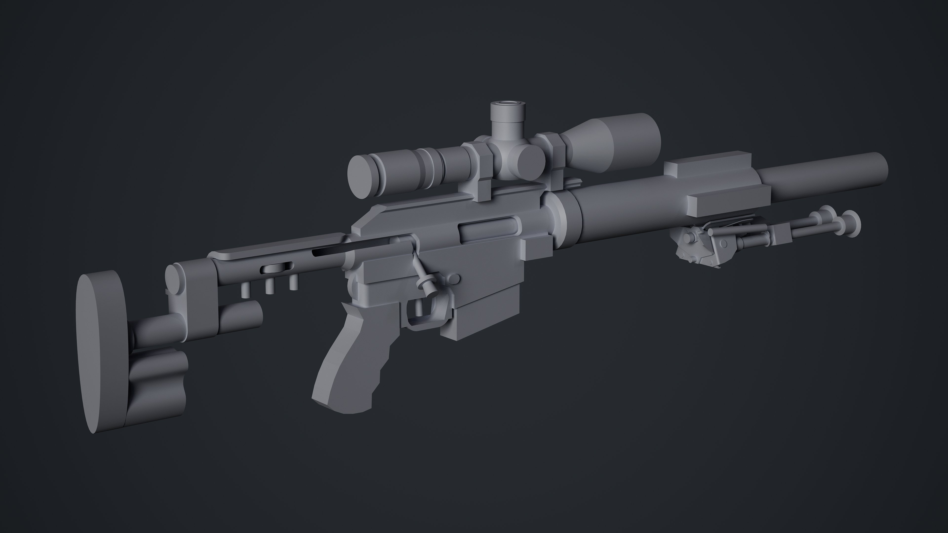
Blockout stage is completed for the whole gun.


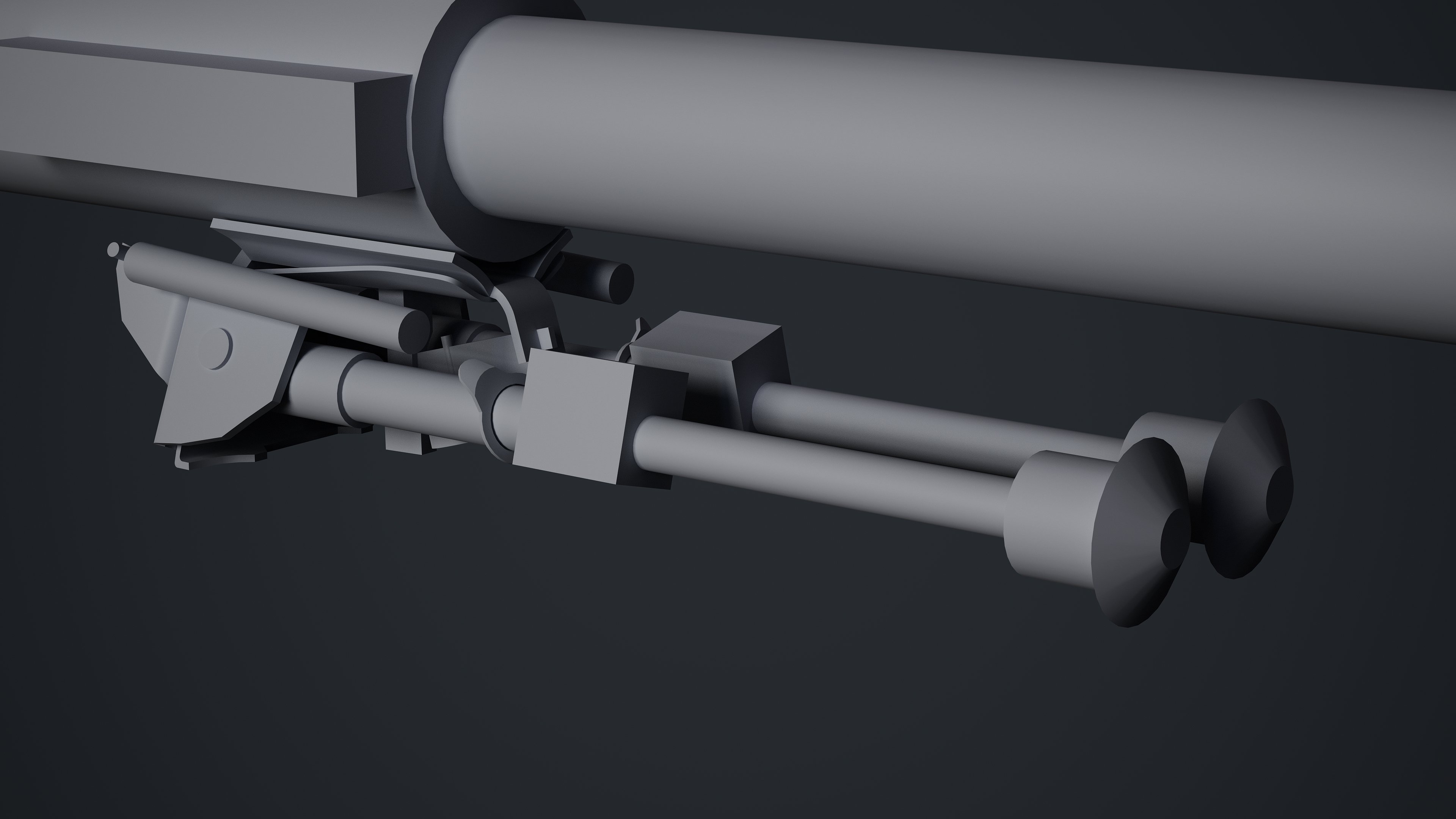
Midpoly versions of parts that are completed so far.
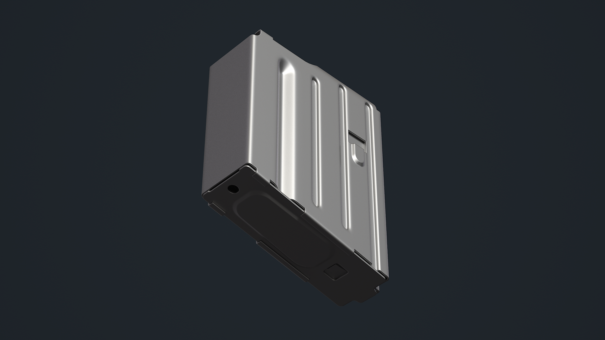
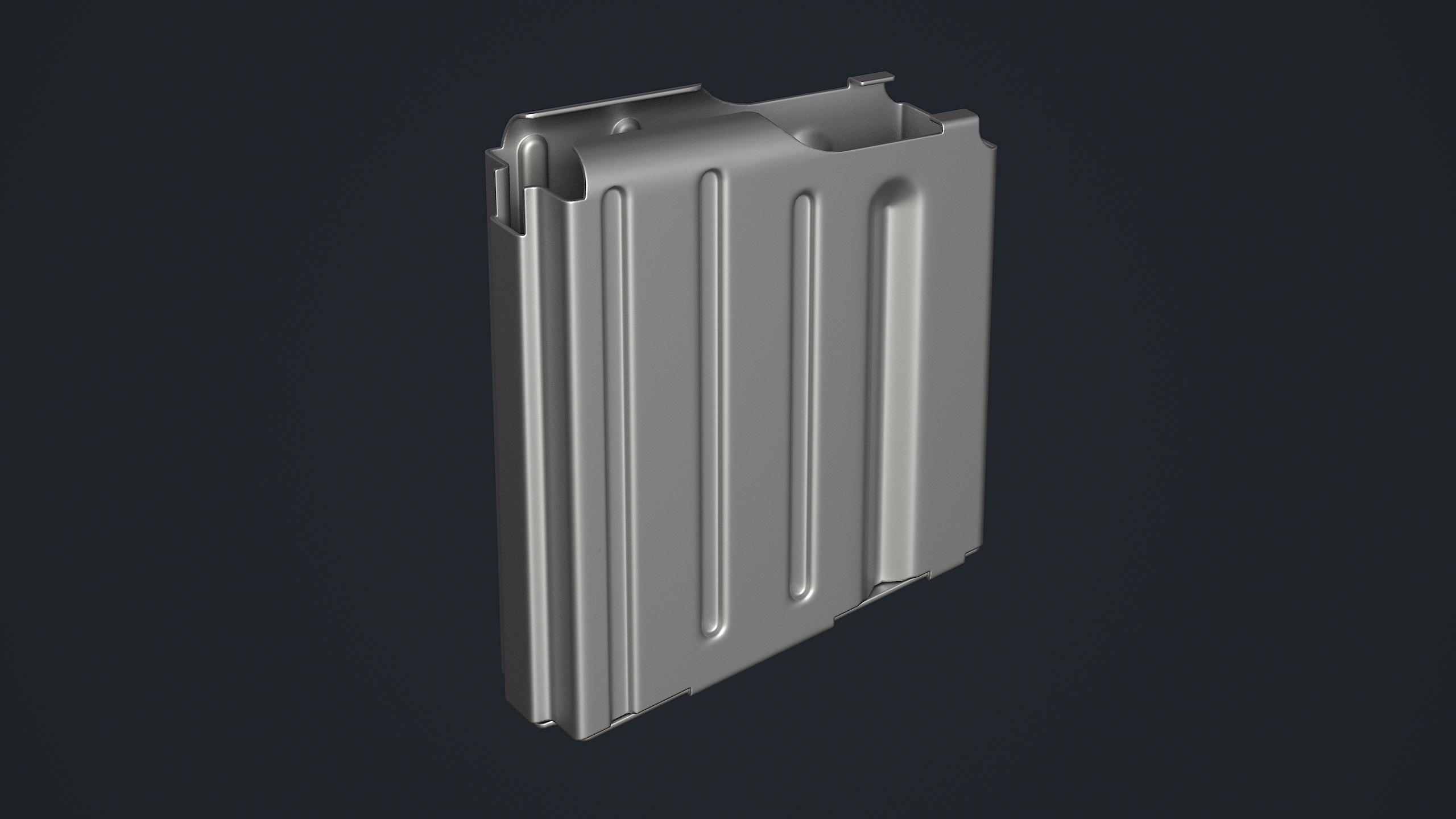
I wanted to refresh my memory on my whole workflow pipeline so I decided to take the magazine to completion. This is the baked version of my lowpoly.

The textured version so far of the magazine. I plan to add more macro wear but I'm also not entirely happy with the results so far, will go through more passes and get some more feedback on this part.
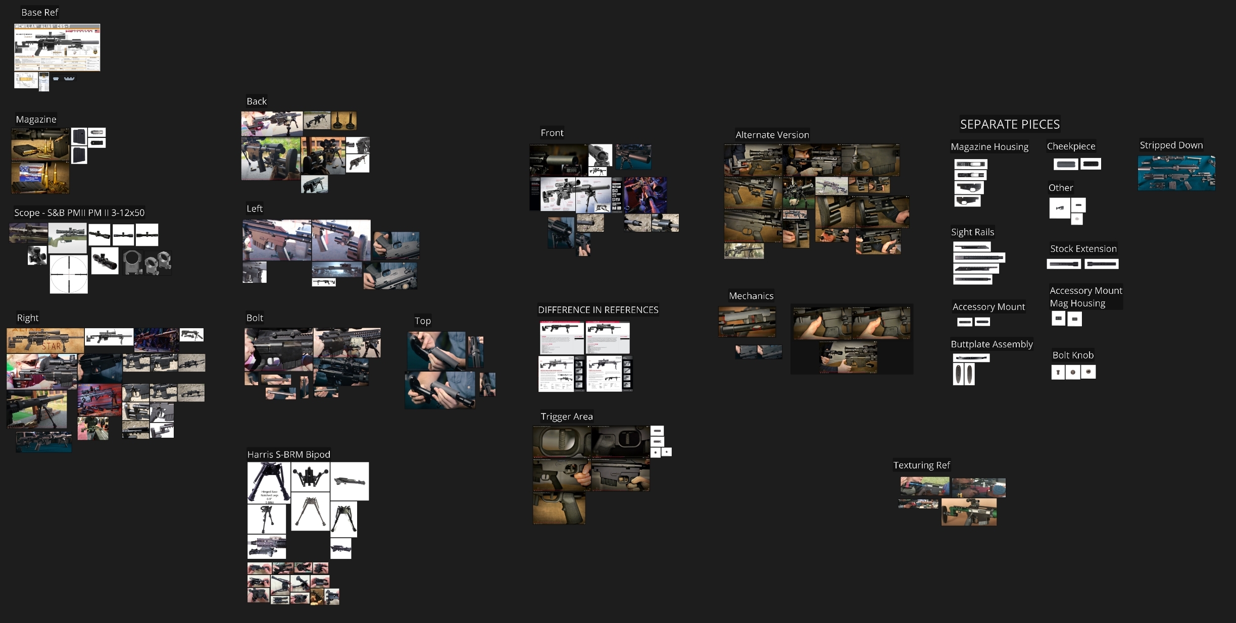
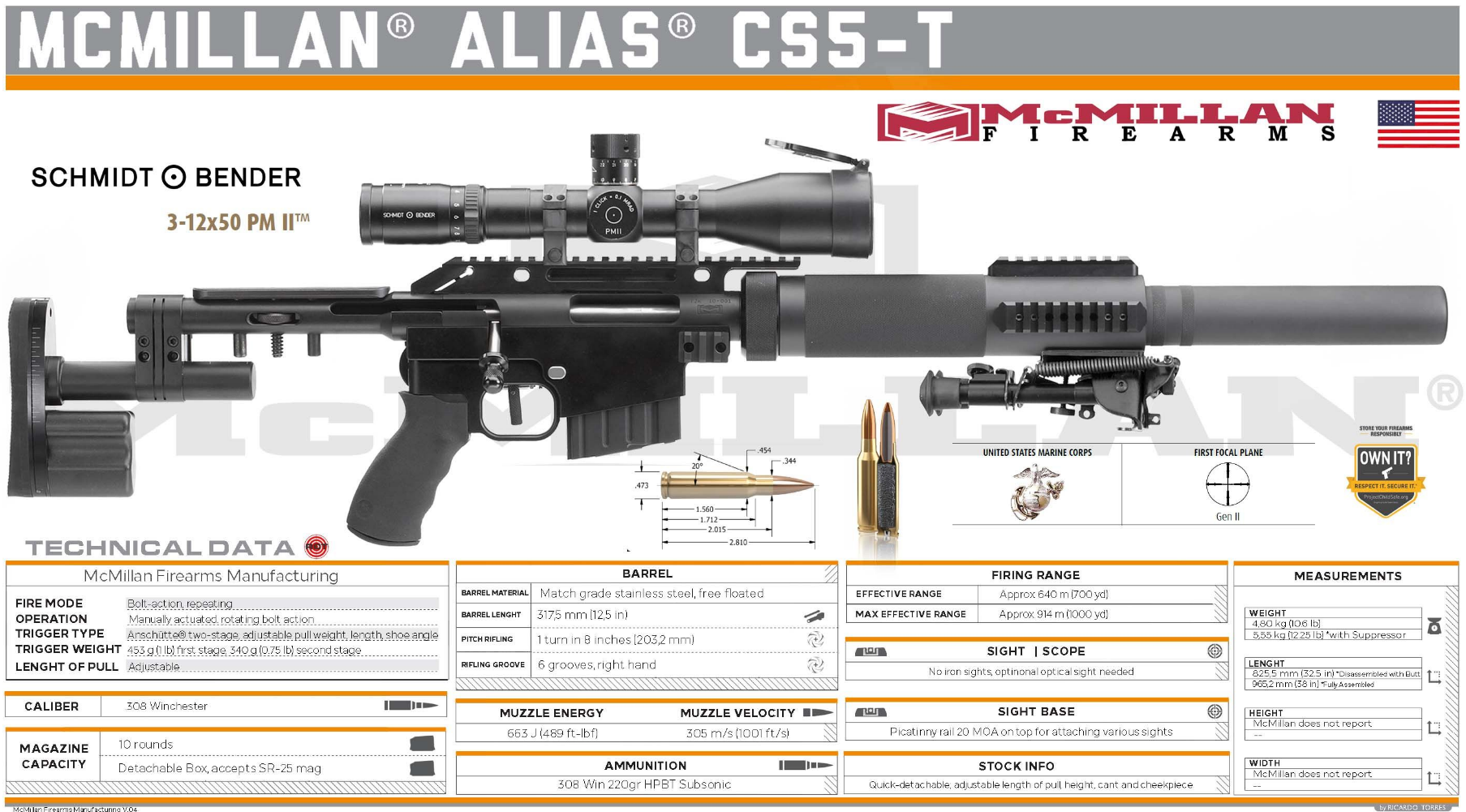
The references that I use.
And that's it for now. I plan to find some free time to keep working on the mag textures and then I'll decide if I want to make a post for that as a warmup or just keep going with the gun as a whole.
Shameless ArtStation plug: https://www.artstation.com/alexanderlindberg
Blockout stage is completed for the whole gun.
Midpoly versions of parts that are completed so far.
I wanted to refresh my memory on my whole workflow pipeline so I decided to take the magazine to completion. This is the baked version of my lowpoly.
The textured version so far of the magazine. I plan to add more macro wear but I'm also not entirely happy with the results so far, will go through more passes and get some more feedback on this part.
The references that I use.
And that's it for now. I plan to find some free time to keep working on the mag textures and then I'll decide if I want to make a post for that as a warmup or just keep going with the gun as a whole.
Shameless ArtStation plug: https://www.artstation.com/alexanderlindberg
3 ·
Re: Scout Hover Bike — Sci-Fi Checkpoint Bay
Thank you! @sacboi Really glad the nose design reads that way. ")
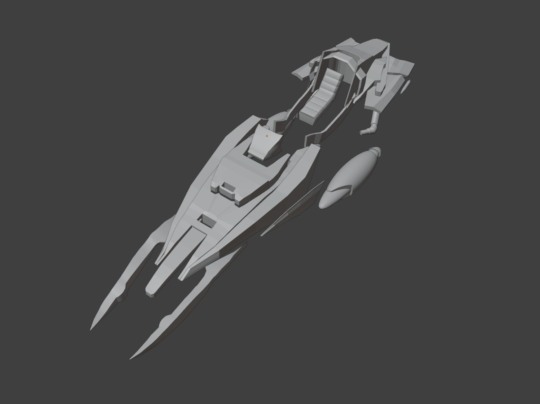
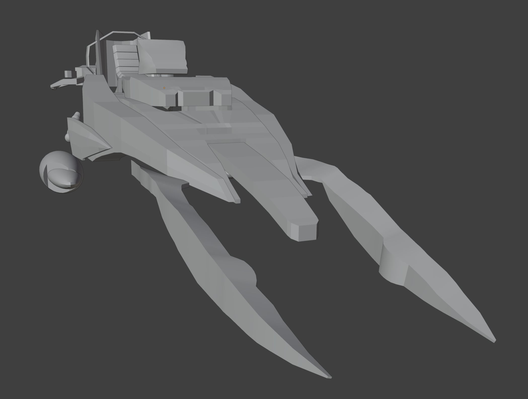
The aggressive split-prong silhouette was one of the main things that drew me to this direction. I’ll try to keep that as a strong feature while making sure the mechanical parts still feel functional and believable.
A brief blockout update:
I’m currently focusing on locking in the main proportions and silhouette before moving into cleaner shapes and mechanical connections. The front prongs, seat area, and rear fins are still rough, but the overall direction is starting to come together.
I've started on the seat and I have all the main pieces finished for the blockout. The gaps and empty spaces, that is where mechanical components will go.
Feedback on silhouette/proportions is very welcome.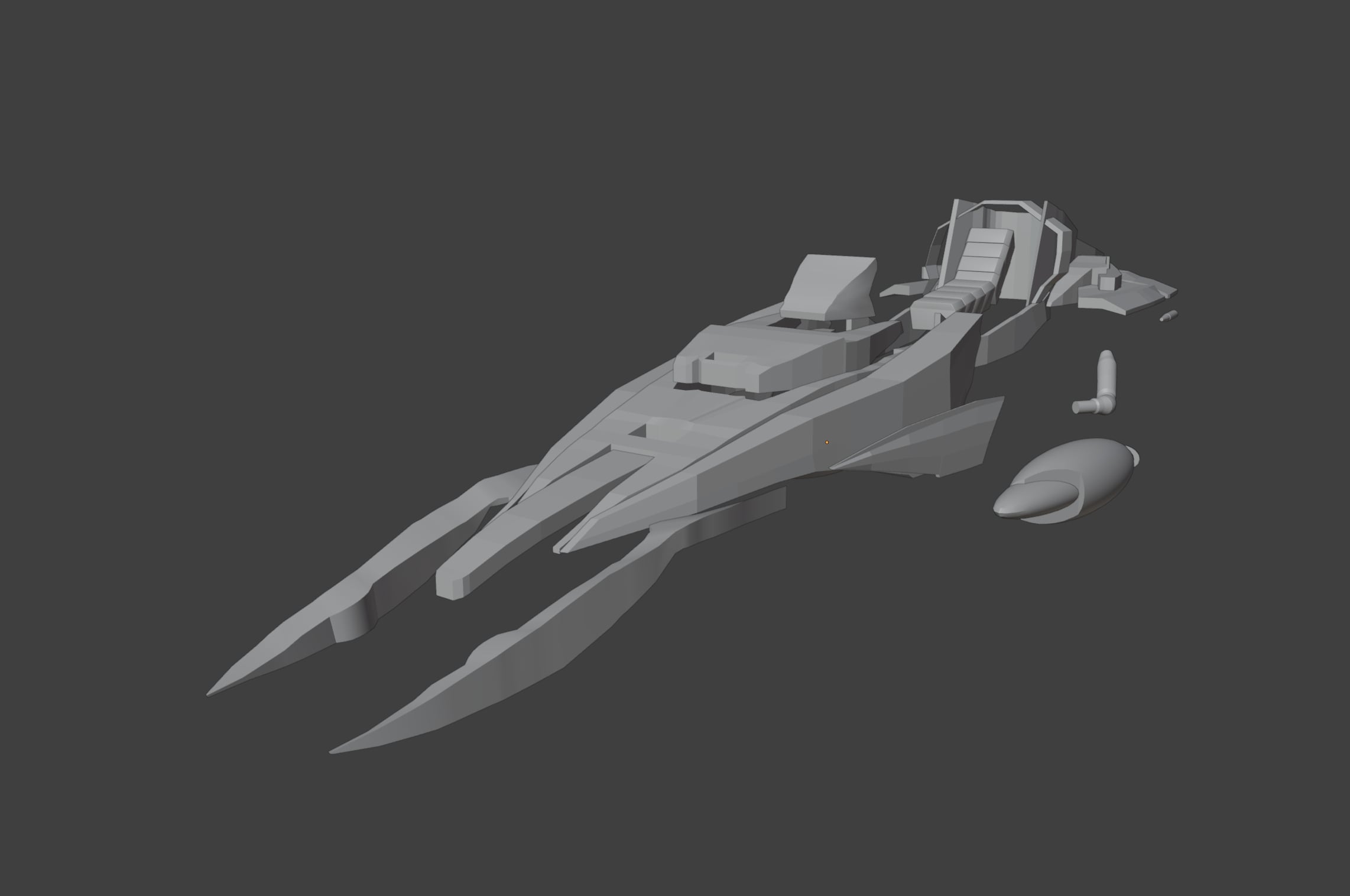
 Vastra
3 ·