It starts May 12, and ends Oct 17. Let's see what you got!
https://polycount.com/discussion/237047/the-brawl²-tournament
The Polycount Newsfeed
Re: Recently hired in AAA? Show us your portfolio
Super excited that I can finally post in this thread! I recently got hired as Environment Artist at Turn 10 to work on Forza! This is my first AAA job!
Here is my small background: After I graduated from the university, I have been working at Miliarty Simulation for the USA Airforce for a couple of years. And then, I worked on the unannounced tv show at BRON for almost a year.
Thank you, everyone on Polycount, for all of the advice, feedback, and support!
https://www.artstation.com/tythomas

 tythomas063
Re: Sketchbook: Frank Polygon
Subdivision sketch: truncated cones.
These examples show how segment matching can be used to join truncated cones to curved surfaces.
When the support loop around an intersecting shape disrupts the segment spacing of an existing shape, it tends to cause unintended deformation that can generate visible smoothing artifacts. Simplifying the support loop routing, by using the geometry of the existing shape to support the shape intersection, maintains consistent segment spacing and helps reduce the visibility of smoothing artifacts caused by abrupt changes in the topology.

Truncated cone joined to cylinder: This will generally behave like a simple cylinder to cylinder intersection. Align the segments in both shapes and simplify the support loops around the shape intersection whenever possible.

Truncated cone with adjacent cylinder joined to cylinder: Adjust the number of segments in each shape to maintain a relatively consistent geometry density while also aligning the edges around the shape intersection.

Truncated cone with radially clocked cylinder joined to cylinder: Start by aligning the segments in the shapes then add perpendicular support loops, as required, to match the support loops around the base of the shape intersection.

Truncated cone with adjacent cylinder joined to truncated cone: Get the alignment as close as possible then constrain any differences in the shapes to the area between the inner and outer support loops around the shape intersections.

Truncated cone joined to chamfered cylinder: Rotate the intersecting geometry as required and adjust the number of segments in each shape to align the edges around the base of the intersection. Perfect alignment isn't always possible but close enough is usually good enough. Perpendicular edge loops can be routed across the intersecting shape or reduced with a triangular quad.

Angled cylinder joined to truncated cone: Steeper tapers and proportionally larger intersecting shapes tend to amplify the difference between the segment spacing around the extreme ends of the shape intersection. Using the minimum amount of geometry required for each shape can help reduce the overall complexity and make it a lot easier to join the two shapes, without generating unintended shape deformations.

Recap: Adjust the number of segments to align the edges around intersections while also preserving the accuracy of the underlying shapes. Simplify topology routing and use the existing geometry to maintain the segment spacing of curved surfaces. Rotate intersecting geometry to align the edges without adding unnecessary mesh complexity.
Re: Sketchbook: Gregory Stoffel
Maikubi
舞首
まいくび
Translation: dancing heads
Habitat: the sea around Sagami Bay
Diet: none; they are driven solely by anger
Appearance: Maikubi are a trio of severed samurai heads which appear on the surface of the sea at night.
Maikubi dance around in circles above the waves trying to bite one another. They spit flames from their mouths, making them especially visible at night. Their dancing creates large waves shaped like tomoe–a symbol that looks like a large comma.
Maikubi bring bad luck as they dance on the sea. Shipwrecks and other sea disasters are said to occur more frequently when maikubi are nearby.
Maikubi come from the local folklore of Manazuru, in Kanagawa Prefecture. They are also depicted in the illustrated Edo period ghost story collection Ehon hyakumonogatari.

 Gotferdom


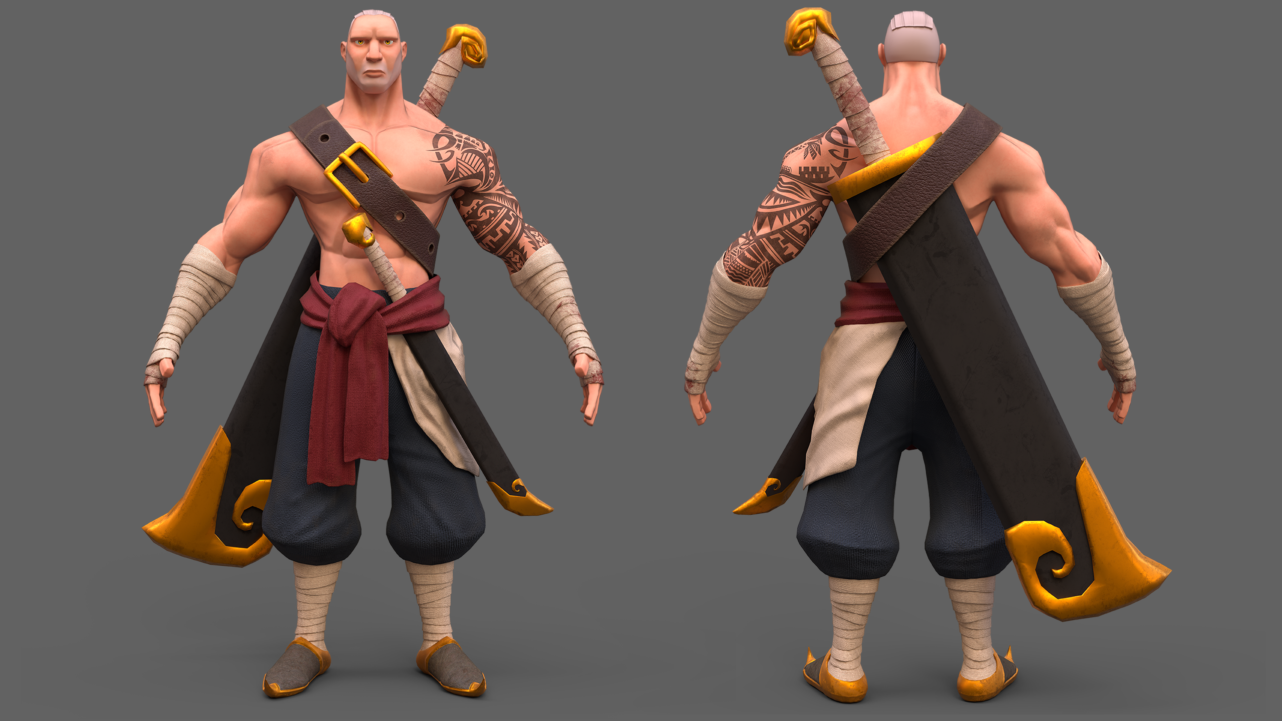
Hunter
Hello! I am finally here to share my latest project,
hope you like it.
Here's my portfolio link and for full res + another render for the character https://www.artstation.com/timothy_feriandy
I am open commissions too by the way and looking for opportunity for full time, freelance, contract and part time, feel free to contact me via Artstation, Discord: timothy #9018 , email: timothyferiandy@gmail.com


 Timothy_Feriandy
Tool for Creating Animated SVGs from SVG keyframes (proof of concept)
Hi,
for an animation project i needed a tool so i can animate my svg keyframes , which i created in Affinity designedr.
my problem is: affinity designer doesnt support animation, and i have a boatload of assets already created in affinity designer and i tried and failed (to some degree) to export it into all sorts of animation software . so after i researched with the possible export formats that i can create animations from my exported svgs via siml animation
so my first successful test was this:

my idea was, if i create some sort of template in [insert vector program with svg support here] , create copys of the file and change the shapes so i have keyframes
and then parse the svgs in my tool, match the shapes and animate them.
at the moment i can only match shapes by id and they have to be compatible (ie have the same amount of commands in their paths), also i am able to animate transformation matrixes , so color gradients can be animated.
my goal is to be able to match the most compatible shape, make it compatible and then animate it (a little like https://shapeshifter.design/ does it, but also using the autoawesome algorithm to find the closest match) so i dont have to manually assign a unique id to every animatable object (because that is tedious, and who wants to do tedious stuff)
also i want to assign frame timing and easing in filenames (i already tried it manually but havent implemented it)
anyway, weird stuff like this is possible with my tool already :

now the big question,
is anyone besides me interested in such a tool?
i can upload it to github , althou its still in a kind of messy state (which is embarassing XD)
Re: Why is triangle used instead of Quad?
To add to what's already been said and hopefully clarify a few things: there's a number of different reasons why an artist would choose to use a triangle instead of a quad when creating an arch. The relevance of any specific answer really depends on the model's intended use and the desired outcome for the project. Looking at those two images, it's not entirely clear whether this model is just a block out or a final low poly.
If it's a block out then it's possible that the triangles provide some additional edges that are required for subsequent modeling operations. Quad corners work well for most linear edge transitions and some types of curved intersections but they can also disrupt the curvature of adjacent edge loops. N-gon corners produce a similar effect.
While it can be beneficial to model with quads and n-gons, triangles can also be useful for pulling support loops inwards along a curve. Below is an example of how quad and n-gon corners can create subtle smoothing artifacts near curved surfaces. Converting these corner faces to triangles produces edge tension that can help reduce the visibility of smoothing artifacts near surfaces that transition from flat to curved.

If it's a low poly model then the mesh may need to be triangulated in certain areas to make seam placement and UV unwrapping easier. While most applications can display quads and n-gons, there are a variety of different triangulation methods and there's no guarantee that the order of the underlying edges and faces will be the same in every application. Which is why it's generally considered best practice to triangulate the final low poly model before exporting for baking and texturing. This will ensure that the model's geometry and smoothing behavior is consistent as it moves through the production pipeline.
Here's an example of just how varied the triangulation methods can be when moving the same mesh between two different applications. This sort of geometry miss match isn't a deal breaker for most simple modeling operations or basic material authoring but it can cause significant issues when working with tangent space normal textures.

Severe gradation in the normal map is often caused by the differences between the shading behavior of the high poly and low poly surfaces. This additional color information is specific to the state of the meshes during the bake. Alterations to the order of the low poly mesh will tend to produce normal artifacts, unless the difference between the shading behavior and baked normal information is resolved.
Which is why normal bakes from meshes without any smoothing splits tend to be sensitive to triangulation changes. The example below shows how the direction and intensity of the normal values changes, based on the low poly's shading splits and edge order.

While it possible to find workarounds for actively controlling mesh triangulation and using smoothing groups, these types of "Never fail, quick and easy!" solutions tend to ignore the fundamentals of established, current generation workflows. Granted there are some situations where it may be beneficial or necessary to use single smoothing groups or add support loops to the low poly or rely heavily on normal data transfers but a lot of the application specific workarounds tend to fall apart when working with a team that uses a wide variety of tools and regularly moves models between applications.
Creating a low poly model with consistent shading behavior goes a long ways towards making tangent space normal bakes a one or two shot deal. Adding smoothing groups is large part of that but controlling mesh triangulation is another important element in the optimization process. A lot of current, industry standard applications use MikkTSpace. Which makes it relatively easy to create assets in a synced tangent workflow. Yes, there are edge cases but that really isn't a good excuse for actively avoiding contemporary tools and workflows for content destine for popular engines like UE or Unity.
While this following example is far from best practice, it does demonstrate that using smoothing splits, in conjunction with a synced normal workflow, is fairly robust when it comes to accidental or unintentional changes in the triangulation after baking. All of the meshes have the same hard edges and only use the texture baked from the quad / n-gon low poly. Much less impressive when considering that the application automatically triangulated the low poly during the baking process but still a reasonable demonstration of how important it is to control the shading behavior with smoothing splits.

As shown below, when using a single smoothing group, even quad geometry doesn't guarantee that the triangulation order won't affect the surface shading and normal data. Using hard edges [smoothing groups] with a synced normal workflow tends to produce clean bakes that can be more resilient but curved surfaces and single smoothing group workflows tend to be more sensitive towards changes to the edge and face order after baking.

Another thing to consider about triangulation order is that the placement of the edges can skew surface details. Which, though it's often quite subtle, can have a negative impact on the overall quality of the bakes. In the example below, the diagonal surface elements have a slight distortion wherever a low poly edge crossed over a change in the high poly's surface.
While it may be possible to resolve some of these issues with a skew map or custom low poly cage, it's worth noting that the low poly that has a triangulation order with similar diagonal edges does have less overall distortion. Simple stuff like this can help avoid unnecessary complexity and extra work that comes with trying to resolve visible baking errors that are caused by letting the software choose the triangulation method on critical areas.

In a workflow with synced tangent space and smoothing splits, edge triangulation in low value areas can be largely ignored, provided it remains consistent during the baking, texturing and importing. However, it is worth running some quick test bakes to evaluate how the current low poly triangulation is affecting areas that are right in-front of the player.
The mesh used to demonstrate these principles is fairly simple, so the issues are quite subtle but carelessness towards these sort of things tends to compound in a way that produces a lot of small errors that bring down the overall quality of a project. Often with no tradeoff for a tangible benefit. Below is a short animation that compares a few different triangulation methods and better highlights how these changes impact the details baked into the normal texture.

There's a lot of great resources on these topics here on polycount and on the help pages of the various texturing applications. Here's a few links that are a good jumping off point for additional self guided learning:
https://polycount.com/discussion/41232/lowpoly-or-the-optimisation-appreciation-organisation
https://polycount.com/discussion/163872/long-running-technical-talk-threads
https://www.youtube.com/watch?v=ciXTyOOnBZQ
https://marmoset.co/posts/toolbag-baking-tutorial/
https://substance3d.adobe.com/documentation/spdoc/baking-109608997.html
Sketchfab Spotlight | October 2022

A collection of the latest and greatest pieces from Sketchfab users