Best Of
Re: Inflating high poly before baking normal map
Well ... one can very well have "years of experience on treeple A" without having any experience working with others - resulting in odd workflows that would never work in production at a studio.
"Hey, we need to rebake this armor set"
"Sure thing - just remember to inflate the high just a tiny bit, otherwise it won't look good"
...
At the end of the day :
- If the highpoly needs to be rounder, make it rounder.
- There is no need for the gap between the low and the high to be filled, because this distance doesn't affect the normalmap. Only *normal* information gets written, not distance.
- If anything, one thing that can happen is that people without much experience tend to surface-snap their low to the high without giving it any second thoughts, resulting in a low that is skinnier than what it should be especially if the density is medium/coarse - hence a final asset with less beef than the reference high. But that's completely irrelevant here ...
I think it would be best for The Mentor to provide some specific, practical illustrations. After all, perhaps some things got lost in translation.
As far as I am concerned the *only* case where I could see such an edit of the high being worth it would be that of a very poorly modeled high with weak/razor sharp edges in need of being fixed as fast as possible.
 pior
pior
3 ·
Re: The Bi-Monthly Environment Art Challenge | May - June (90)
I didnt have much time but I managed to finish my high poly and do some unwrapping for my low poly. 
3 ·
Re: Tech Artist - What are you working on: FOREVER Edition!
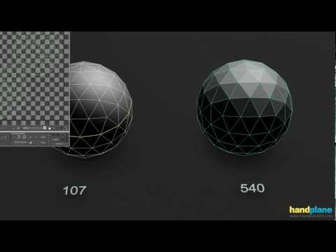
added some phong specular lighting to a normal mapped camera facing shader.

the top and bottom spheres are actual spheres for reference all the others are just quads which in reality looks like...

though enlarged somewhat.
something a bit more subtle...

probably not that subtle") without the phong spec....
without the phong spec....

the top and bottom spheres are actual spheres for reference all the others are just quads which in reality looks like...
though enlarged somewhat.
something a bit more subtle...
probably not that subtle
 Klunk
Klunk
3 ·
Re: Why is it recommended to make all UV seams hard?
In general: hard edges require corresponding UV splits for padding but UV splits do not require hard edges.
Hard edge placement is about controlling low poly smoothing
behavior and baked normal gradation. UV seam placement is about
optimizing usable texture space while also limiting texture distortion.
Bringing the two together it's about balancing visual quality with
resource efficiency. Using fewer hard edges and UV splits tends to be
more resource efficient but it's also important to make sure the final
product looks good.
There is an individual resource cost to both UV splits and hard edges but once the mesh is split by either it's split so stacking them doesn't incur additional overhead beyond the first split. This is one of the reasons why it's generally considered best practice to strategically pair and place hard edges and UV seams along natural breaks in the shapes.
Hard surface modeling tends to naturally produce shapes that have a lot
of matching UV splits and hard edges but this is less common on organic
shapes. The idea that every UV seam on every model needs to have hard
edges is unconventional. There may be some edge cases where this is done for artistic or technical reasons but it wouldn't be standard practice.
Bellow is some additional documentation that explains these concepts in detail.
Marmoset Toolbag baking tutorial:
https://marmoset.co/posts/toolbag-baking-tutorial/
https://marmoset.co/posts/toolbag-baking-tutorial/?page=Map Types#maptypes
https://marmoset.co/posts/toolbag-baking-tutorial/?page=Toolbag Setup#basics
https://marmoset.co/posts/toolbag-baking-tutorial/?page=Best Results#bestresults
https://marmoset.co/posts/toolbag-baking-tutorial/
https://marmoset.co/posts/toolbag-baking-tutorial/?page=Map Types#maptypes
https://marmoset.co/posts/toolbag-baking-tutorial/?page=Toolbag Setup#basics
https://marmoset.co/posts/toolbag-baking-tutorial/?page=Best Results#bestresults
Controlling shading behavior by Alec Moody:
 https://www.youtube.com/watch?v=ciXTyOOnBZQ
 FrankPolygon
4 ·
Re: How The F*#% Do I Model This? - Reply for help with specific shapes - (Post attempt before asking)
@JBurk The underlying topology in both your examples, with some minor adjustments, could work. Which starting topology layout makes the most sense will depend on whether the shapes need a softer or sharper transition.
With subdivision modeling there's almost always going to be some kind of minor smoothing imperfection and it's important to consider whether or not this will be visible to players at normal view distances. If the smoothing artifacts are confined to a small area that isn't going to be regular focal point then there's often minimal benefit to spending a large amount of time removing the artifacts. When working on small details it's important to zoom out every once in a while and evaluate the overall read of the object's shapes and edge width highlight.
One thing to watch out for is edge width consistency: If the actual parts are made from a single material (like metal) then try to avoid inconsistent support loop widths around the major forms as this tends to muddy the visual read of the object. Parts cut from metal plates or machined from billets and precision castings tend to have a relatively consistent sharpness to their shapes. Rough cast parts tend to have soft shapes like draft, fillets and round overs that are interrupted by sharp machined surfaces. Mass produced plastics tend to have much softer edges and transitions with a lot of variation.
A couple of posts up there's a discussion about a similar shape with an intersecting cylinder that sticks out from a flat surface and that post has additional links back to a similar discussion on page 178 about blending rounded rectangles.
When blending curved surfaces into other shapes there's two basic approaches: placing the intersecting geometry on the existing edges that make up the cylinder walls and adding the support loops around the intersecting shapes or placing the intersecting geometry between the existing edges that make up the cylinder walls and using this existing geometry as support. It's also important to use the appropriate amount of geometry in the cylinder to ensure there's both enough room for additional support loops and enough geometry to hold the shapes without introducing cylinder wall deformation.
Below is an example that shows the basic topology progression for each approach. Top row is placing the intersection on the existing geometry in the cylinder and the bottom row is placing the intersection between the existing geometry on the cylinder.

Here's a comparison of wide and narrow support loops placed around the shape intersection generated by placing the intersecting shape directly on the existing geometry in the cylinder wall. To maintain all quad geometry this topology routing requires the number of segments in the cylinder match the topology around the corner of the intersecting rectangle.

Here's a comparison of wide and narrow support loops with a different topology routing that doesn't require exact segment matching between the cylinder and the intersecting rectangle. In this example the intersecting shape is placed directly on the existing cylinder wall geometry.

Here's a comparison of wide and narrow support loops when the existing cylinder geometry is used to support the shape intersection. Both shapes are placed with a slight offset and merged. This offset provides space for additional support geometry without disrupting the smoothing behavior of the curved surfaces.

There's a number of ways to handle the topology around this type of shape intersection and which layout makes the most sense will depend entirely on constrains from adjacent geometry, tools used to generate the support loops (manual placement with loop cut tools or automatic placement with modifiers) and overall mesh quality and shape accuracy goals. Most of these topology strategies work with or can be adjusted to work with modifier base support loop placement.
As far as the all quads requirement: there's a number of great discussions in this thread about how to use triangles and n-gons appropriately. Working under self imposed, artificial restrictions can really have a negative impact on the amount of time required to model a given shape and the overall quality of the final mesh.
It's important to compare different topology layouts on ease of modeling, smoothing behavior quality, edge highlight consistency, editing flexibility and topology cleanliness, etc. Blindly following popular mantras like "quads only" and "manual loop placement is superior" can really lead to some nasty habits that become massive time sinks without offering any tangible improvement to the final product.
FrankPolygon
4 ·
Re: How The F*#% Do I Model This? - Reply for help with specific shapes - (Post attempt before asking)
@viqhaas Welcome to Polycount. Consider checking out the forum information and introduction thread.
Overall it looks like you have a pretty good start with the base mesh and will just need to adjust the support loop routing on attempt 2.
The vertical deformation in both attempts is caused by the support loops that run off the back of the tabs and down into the hemisphere where they disrupt the even spacing between the segments. There's a few different ways to resolve this so what's going to work best will depend on what the project constraints are.
If keeping the current mesh density is important then it should be possible to simply terminate the support loops into n-gons at the base of the shape intersection. There will be some minor shape deflection and subtle artifact but it will be limited to the very small transitional area around the shape and it's unlikely that it will be visible when the normal textures are baked down.
If a greater degree of shape accuracy is important then it will be necessary to increase the number of segments in the hemispherical base mesh so the support loops around the tabs can flow into the existing geometry around the shape intersection.
The horizontal deformation around the top of the shape intersection is caused by a lack of supporting geometry above the area where the two shapes merge. This can be resolved by simply placing a support loop (directly above the shape intersection) at the bottom of the tabs.
With subdivision modeling: Preserving the shape of the underlying geometry and either limiting the deformation to the small transitional areas around the shape intersections or consistently averaging out the deformation over a wider area will help reduce the severity of smoothing artifacts. Increasing the amount of geometry tends to increase the overall shape accuracy but also tends to reduce editability.
This is where balancing shape accuracy and modeling efficiency becomes important. Evaluate how closely the object will be viewed and determine how much geometry is required to accurately hold the shapes. If minor smoothing artifacts aren't visible at normal viewing distances then there's minimal benefit to spending a significant amount of time improving the results. Use the appropriate amount of geometry for the project's goals and the model's use case.
Here's an example of what this process could look like using a similar mesh density to attempt 2. The existing geometry in the hemisphere acts as support around the base of the intersection and the narrow support loops that sharpen the tabs simply end as n-gons on the surface of the hemisphere. A horizontal support loop is added directly above the shape intersection to control the upward deformation of the shape transition and can be moved up or down to adjust the width of the shape transition.

Here's another example that shows what this process could look like when geometry density of the hemisphere is increased to match the number of supporting segments in the tabs.

How much geometry is required depends entirely on how accurate the shapes need to be and how closely the model will be viewed. Triangles and n-gons are fine as long as they aren't causing any major smoothing artifacts at normal viewing distances. It's also helpful to try and maintain a relatively consistent edge width across similar materials since this will unify the shapes and the highlight roll off. Narrower (sharper) support loops read more like metals and machined surfaces while wider (softer) support loops read more like plastics and molded parts.
The last half dozen pages in this thread have a lot of great examples of common shapes and smoothing artifacts so it's worth taking the time to skim through this thread and see how other artists have solved similar smoothing issues.
FrankPolygon
3 ·
Re: How The F*#% Do I Model This? - Reply for help with specific shapes - (Post attempt before asking)
@Suosa It looks like you're on the right track. If the mesh subdivides cleanly, without any major smoothing artifacts,
then it's generally acceptable to use n-gons and triangles in hard
surface subdivision models.
Since this model is going through a sculpting pass it may make more sense to try and add these minor surface defects in ZBrush. A boolean re-meshing and detail sculpting workflow may be more efficient than trying to perfect all of these small details on the subdivision base mesh for the high poly sculpt. If including the larger surface defects in the subdivision mesh is a stylistic choice then just route the support loops around the major shapes and try to constrain any n-gons or triangles to the flat areas.
Extremely narrow support loops tend to produce a tight edge highlight
and although it can look good up close it may be difficult to read from
regular view distances. Over sharpened edges can also cause baking
issues so consider using a slightly wider and more consistent edge width
across the entire shape.
Below is an example of what this could look like: block out the basic
shape, add the larger surface defects and route major support geometry
as necessary. Add support loops (highlighted) around the edges that
control the major shapes using a bevel / chamfer operation.
It should be
possible to control the bevel / chamfer placement and
behavior with groups or weights. Review the documentation for your
application to find the correct settings combination that allows you to
reliably place support loops with automated tools. Try to avoid having
to manually place or adjust support loops.

@IronLover64 Overall it looks like you have the right idea. Try to use a little less geometry when blocking out the shapes and use inset operations when creating the screens and desk spaces so there's room around the shapes to add bevels. Also try changing the bevel geometry settings from Sharp Miter Outer to Arc Miter outer.
Here's an example of what this process could look like.
Start with a seven segment circle and multiply the segment count using 7*N until there's sufficient geometry. Use a series of inset operations to create the truncated cone in the center of the table. Select a section of the truncated cone's wall and use an inset operation to create the screen's outline. Run another inset operation to create the depth and use the loop cut tool to add support geometry through the screen. Repeat this process to create the desktop on the table below the screen. Split the table into a single 1/7th section. Add bevel weight to the highlighted edges and add a bevel modifier. Merge in any additional details. Spin duplicate or object offset array duplicate the 1/7th section and merge vertices by distance. Add a subdivision modifier.
 FrankPolygon
3 ·

Re: Show your hand painted stuff, pls!
Hello everyone, I drew a lot of things here, my favorite props.
-
Всем привет, я тут много чего нарисовал, свои любимые пропсы.


 Gruno_Kromer
4 ·
Re: How The F*#% Do I Model This? - Reply for help with specific shapes - (Post attempt before asking)
@jdellinger98 Overall you have the right idea: using instancing, mirroring and other modifiers will reduce the workload and speed up the modeling process. Try to maintain a consistent shape transition when working with intersecting geometry on curved surfaces.
Using a single base model for the high poly and low poly.
It is possible to have a single base mesh that can be build up into a high poly cage mesh then quickly optimized down into an in-game low poly model. When taking this approach it's going to be important to consider factors like view distance, texture layout / size, damage states and in-game poly count limitations before committing to any modeling. All of these factors will help set a technical target for the low poly model and these restrictions will help inform how dense the base model should be.
This approach probably makes the most sense if the flutes on the column actually need to be in the low poly model. In cases like this, where the high poly and low poly model need to share a lot of surface details, this approach makes sense and can be very efficient. However, there's also a lot of situations where the in-game model doesn't need to be this detailed and in those cases this approach doesn't make sense because it would add artificial restrictions and unnecessary complexity to the modeling process.
Avoiding deformation around the perimeter of flutes on a curved surface.
It's likely (based on the description and images provided) that the undesired deformation of the cylinder around the fluted details is caused by too much manual mesh manipulation and the addition of excess geometry between the existing edge segments that make up the wall of the cylinder's shape. With subdivision modeling and curved shapes it's important to maintain the consistency of the cylinder's shape while also ensuring that the perimeter of intersecting geometry remains concentric with the walls of the underlying cylinder.
In general: It's important to match the segment counts of intersecting shape geometry whenever possible and it's considered best practice to maintain a relatively consistent segment spacing around the walls of cylindrical shapes. When matching up the segments of intersecting features it's also considered best practice to use the existing geometry of adjacent shapes as support by placing the intersecting geometry between existing edge segments. The last few pages has a number of good discussions on how this can be done.
The big thing is to keep all of the new geometry in line with the curvature of the cylinder walls.
Here's an example of what this could look like: Using a bit less geometry will make the mesh more efficient and potentially easier to work with. It's also worth noting that the intersecting geometry on the curved portion of the flutes lines up with the existing geometry of the cylinder wall segments. A flat walled flute wouldn't be an impossibility but rounded profiles seems to be more common for Ionic columns. Depending on how accurate the model needs to be it may be worth researching the exact flute profile for a specific structure or period.

Using triangles and n-gons.
Provided the mesh subdivides cleanly, without any major smoothing artifacts and barring any legitimate technical limitation, it's acceptable to use triangles and n-gons in a subdivision cage mesh. Whether or not this is acceptable depends entirely on the result and the workflow. It can be very easy to waste time and resources perfecting things that might not really matter in the long run.
The triangle on the flat area inside the volute at the top of the capital isn't causing any major smoothing issues so it should be fine. If the end goal of the project is to create a game ready asset then focus on what players are going to see. For most projects, it's extremely unlikely that players will see or care about high poly wire frames.
Here's a similar example that has several n-gons and a significant number of triangles. Most of the sloppy topology is confined to either the flat areas or minor shape transitions so minor smoothing artifacts aren't blatantly obvious. The base mesh will become all quads when it's subdivided and if it's going into ZBrush for a sculpting pass then automated quad re-meshing will provide a clean output. Either way: once everything is baked down and additional high frequency normal details are added any minor smoothing artifacts won't be visible.

Here's another example that shows how a simplified base mesh (with a few n-gons and triangles) can be built up into a high poly model by adding support loops with a bevel / chamfer modifiers. This makes it easier to adjust the edge width and add additional details before sending the high poly out for sculpting / baking. For the low poly the base mesh could be unwrapped and used as is or further optimized to meet any technical requirements.

This circles back to the opening discussion about figuring out what the
players will be looking at and how detailed something needs to be. Often
it doesn't make a lot of sense to spend extra time on something that
doesn't directly improve the visual quality of the model or directly
impact the story / game play. Focus on results and improving the visual quality of what the player will see up close or directly interact with.
To recap:
Evaluate how a model will be used and what the technical requirements
are before jumping in and committing a bunch of time to creating an
overly complex model. Minor smoothing artifacts may not be be visible in
the final bakes or when normal texture details are added.
When working with curved topology try to maintain a
relatively consistent segment spacing, match the segments of
intersecting geometry whenever possible and use existing geometry as
support loops.
If a subdivision mesh subdivides cleanly, without any major smoothing
artifacts and provided there's no technical limitations, it's fine to
have triangles and n-gons in a base / cage mesh.
FrankPolygon
3 ·