The BRAWL² Tournament Challenge has been announced!
It starts May 12, and ends Oct 17. Let's see what you got!
https://polycount.com/discussion/237047/the-brawl²-tournament
It starts May 12, and ends Oct 17. Let's see what you got!
https://polycount.com/discussion/237047/the-brawl²-tournament
Best Of
Re: Stylized Stubby Flintlock Pistol (WIP)
Design Process
Did some digging and found my design process sketches I made for the initial design.Just added some explanation to the different stages.

Initial design sketches.
And here's how I built upon the initial design, adding functional details and refining the overall shape.

Re-sketch of the initial design (top right) and, after some studies (top left), building of the individual parts; assembled (bottom right) and exploded (middle).

Further exploration and refining of the silhouette.
 domfiglhuber
4 ·
Re: Sketchbook: sacboi


Represents about 12.5 hrs + breaks & revisions, really smashed finish up next sesh.
_______________________________________________________________________________________________________________________________________________
March 4 2021


 sacboi
3 ·
Re: Sketchbook: sacboi
First Portrait Complete.
Which was fairly straightforward, less fiddly than initially thought and not bad if I may shamelessly say so myself 


Next one up, IG-11 mech...
sacboi
3 ·
Re: Sketchbook: sacboi
Well, apparently there's more too drawing with curves than I'd initially thought...and then some O_o
So after peeping various resources, had eventually settled upon a proprietary budget option as opposed to a wholly FOSS paradigm simply to make the learning process less mind bending grindie-'ish for yours truly. However that said will definitely revisit an Inkscape vector workflow sometime in the foreseeable future once I've calibrated an intuitive, efficient, personal 2D 'painting with shapes' methodology which hopefully taking another crack at carrying *my ride* project above toward completion! that may or may not accrue : )
Anyways, resulting output thus far over (on 'n off) 2 month tinkering 'under-the-hood' session/s


edit:
at the moment working on generating front & rear 3/4 views
sacboi
3 ·
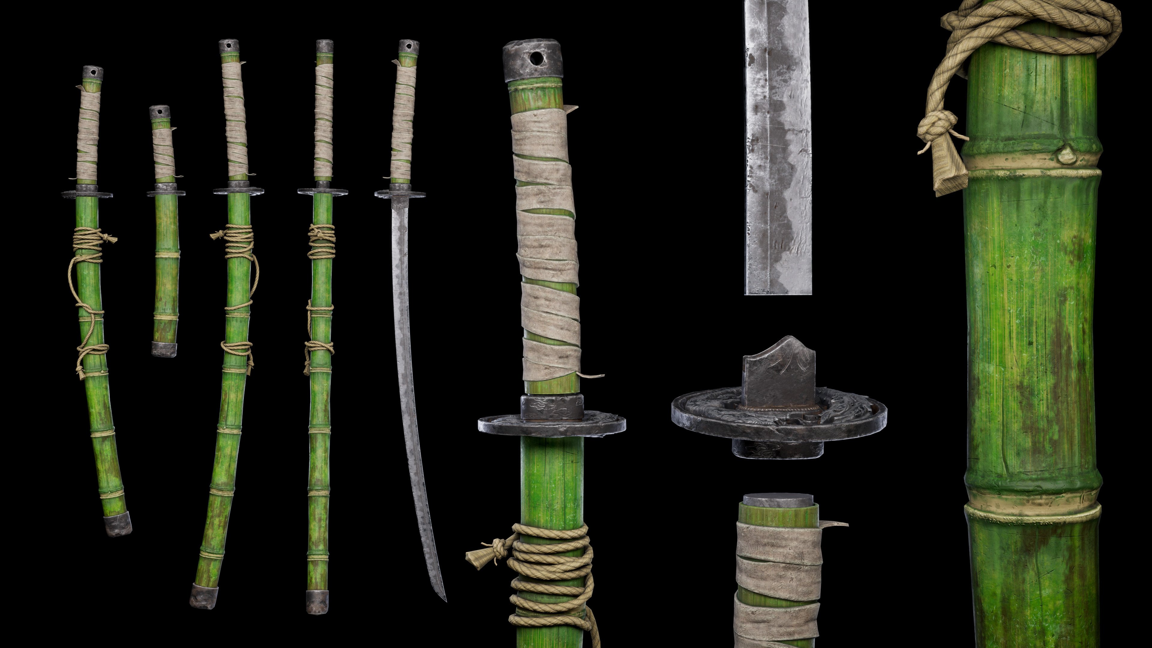
[FINISHED] Game-Ready Bamboo Katana
A sword kit of a poor samurai
hope you guys like it") i made it as a game-ready modular assets
i made it as a game-ready modular assets
Modelled in Blender, textured in Subtance Painter and rendered in Unreal Engine 5
Follow me on Artstation: https://manhha_khan.artstation.com/ !


hope you guys like it
Modelled in Blender, textured in Subtance Painter and rendered in Unreal Engine 5
Follow me on Artstation: https://manhha_khan.artstation.com/ !
 manhha_khan
4 ·
Re: AI Art, Good or Bad? A (hopefully) nuanced take on the subject.
"People want genuine things, like actual paintings", some say.
Two years after this thread was originally starated here is where we are now : "Instagram artists" scamming museums with their tracing-to-canvas-and-color-matching-within-the-lines of Midjourney slop.
This being unnoticed by a whole team of museum employees goes to show that people outside of the tech world are so incredibly uneducated on these topics. I suppose the silver lining is that at some point it's going to become so very obvious, since everyone can learn how to trace and color from reference in about a weekend.
 pior
pior
3 ·
[WIP] - Game Ready Stylized 3D Character
Hey Everyone!
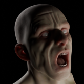
I am working on a game ready stylized character for my portfolio, I am almost done with the highpoly of the character (both ZBrush viewport capture and EEVEE test render are shared). The concept art is by Márcio Vieira. After completing the highpoly I plan to start creating the lowpoly (aiming for around 30k tris), and then texture in substance painter (my goal is 4 texture sets at max with 2048 resolution).
I also plan to model her little robot companion. I haven't really figured out how to make pockets with depth which can also be baked cleanly and are game ready.
I aim to have a optimized character with a nice presentation that would be a decent piece that showcases my skills for my portfolio. Any and all feedback is welcome!
Concept Art
ZBrush Viewport
Blender Render
 egeguncu
3 ·
Re: The Bi-Monthly Environment Art Challenge | November - December (99)
Okay! I'm finishing it!!!
Not done yet, BUT I made some good progress for the past two days. I fixed some stuff with the bake and have been mostly just texturing.
My goal for this pass is just to get all the parts organized and with some sort of texture on them. I've done about 4 hours of texture work on this from last time. Here is my progress so far:


Added decals for gauges, ON/OFF buttons and decals for canisters. Added materials to most things including wires and a lot of secondary geometry.


Any feedback is much appreciated! I'll still be working on it this weekend and hopefully finish by Sunday. I have other projects needing my attention, but couldn't leave this like this!!
Next thing I gotta figure out is how to do see-through glass in Substance...
Not done yet, BUT I made some good progress for the past two days. I fixed some stuff with the bake and have been mostly just texturing.
My goal for this pass is just to get all the parts organized and with some sort of texture on them. I've done about 4 hours of texture work on this from last time. Here is my progress so far:

Added decals for gauges, ON/OFF buttons and decals for canisters. Added materials to most things including wires and a lot of secondary geometry.
Any feedback is much appreciated! I'll still be working on it this weekend and hopefully finish by Sunday. I have other projects needing my attention, but couldn't leave this like this!!
Next thing I gotta figure out is how to do see-through glass in Substance...
 fairlyBread
3 ·
Re: [WIP] - Game Ready Stylized 3D Character
Love it so far!
The crease between the neck and jawline is a bit too crisp I think, where it approaches the ear you could soften it considerably. Right now it makes it look almost like her head is a separate mesh.
Her arms could use more fat, less muscle definition. In the concept notice the flow of the shapes from shoulder through elbow to wrist, it's very soft, and how she really doesn't have wrists.
The crotch looks a bit like a shelf, rather than a clothing crease. Could use some clothing reference to help with this. It's especially noticeable because with the lighting this is the part of the model with the most focal contrast, so it tends to draw the eye.
Why would the pockets have depth? With a cartoony character, to put a hand in a pocket you could just sink the hand into the body just above the pocket.
Her eyes could use a bit more finesse to suggest eyelids I think.
 Eric Chadwick
3 ·
Re: Sketchbook: Zetheros
Created lowpoly & subdivision levels for the male swamp abyssal. Concepted new playable iron automaton 'subrace' of the bronze automatons (technically 'new species' but robots aren't technically alive so they technically wouldn't qualify as a species. Semantics are fun...) for Project Nova.


Have a great week!
Have a great week!
 zetheros
4 ·