It starts May 12, and ends Oct 17. Let's see what you got!
https://polycount.com/discussion/237047/the-brawl²-tournament
Best Of
Re: Sketchbook: Frank Polygon
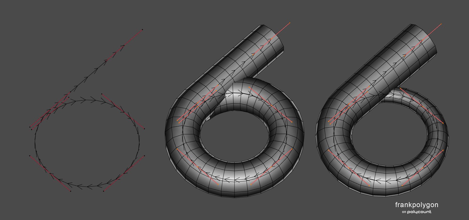
Subdivision sketch: turbocharger compressor housing.
This write-up is a brief process overview that shows how segment matching, during the initial block out, can make blending complex shapes together a lot easier. The order of operations and choice of modeling tools may be different for each shape but the important thing is to try and match the geometry of the intersecting meshes. Getting everything to line up is mostly about creating curved surfaces with a consistent number of edge loops that are shared between the adjacent shapes. Solving these types of topology flow issues early on in the modeling process is one of the keys to efficient subdivision modeling.
For this example, it made the most sense to start with the largest shape first, because it was the most complex. Since curves can be used to generate procedural geometry, it's a fairly straightforward process to adjust the density of the circular cross section, number of segments along the path and taper the end of the spiral. This flattened helical shape was created by splitting a Bézier circle, extruding one side and adjusting the curve's geometry settings.
The center of the housing was created by outlining the shape's profile then using a modifier to sweep it the same number of segments as the adjacent shape.

Details like the outlet flange can also be sketched flat then extruded and rounded over with modifiers.
Smaller surface details are added towards the end of the block out. Since the base shapes are still procedural geometry, it's fairly easy to adjust the number of segments in the larger shapes so all of the circular bosses are supported by adjacent geometry.

Once the block out is completed the shapes can be merged with boolean operations. Any stray geometry can be removed or blended into the existing shapes with operations like limited dissolve, merge by distance, snap merge, etc. It may also be necessary to make room for the support loops by moving some of the vertices along the surface of the shapes. However, most of the topology flow issues should resolve cleanly because of the segment matching.
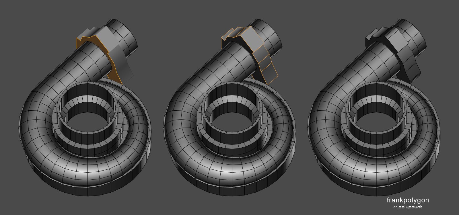
After the base mesh is completed, a chamfer modifier can be used to generate the support loops around the edges that define the shapes. (Highlighted in the example below.) Using a modifier to add the support loops isn't strictly necessary but it helps preserve the simplicity of the base mesh. Which makes it a lot easier to adjust the shapes and sharpness of the edges when the subdivision preview is applied.

Below is what the final base mesh looks like, along with a couple of mesh previews with the chamfer and subdivision modifiers active.

While it is possible to manually create these shapes and try to plan out all of the segment counts ahead of time, using procedural geometry generated by curves and modifiers makes the process a lot easier. It's also important to try and solve most of the topology flow issues at the lowest level possible. This will help prevent a lot of unnecessary work whenever the mesh density has to be increased to support smaller details.

Another thing to keep in mind is that efficient subdivision modeling is often about making tradeoffs that compliment the model's intended use. The important thing is to try and balance accuracy and efficiency. In the context of high poly modeling for game assets, segment matching doesn't always have to be perfect. More often then not, close enough will be good enough.
Recap:
Evaluate the shapes in the references and figure out which part constrains the rest of the nearby surfaces. Establish the block out using a reasonable amount of geometry. Match the number of segments in the intersecting geometry to the adjacent shapes. Try to maintain consistent distribution of edge loops along curved surfaces. Rely on specific tools and modifiers that can generate accurate geometry to make things easier. Solve major topology issues before subdividing and adding smaller details.
Re: Non-Overlapping UVs for game engines
We get a lot "i use zbrush only" applications. They dont know how to create uvs or topo.
Re: The Bi-Monthly Environment Art Challenge | May - June (78)
Exciting concepts! I started with the flooded library too and will try to keep the project short and simple. My main goal is to get more familiar with UE5, especially lighting/reflections. Any idea how to create the water in a way that the windows will shine through? 🤔
@Its0urFate Nice progress! I agree, the animated presentation is very cool 👍️ Are you going to use baked or fully dynamic lighting? Keep it up!

 Fabi_G
Re: The Bi-Monthly Environment Art Challenge | May - June (78)
Getting my blockout started! Excited to be participating in my first art challenge here. Good luck everyone!
 Its0urFate


Sketchfab Spotlight | April 2022

A collection of the latest and greatest pieces from Sketchfab users
Re: [2D Art] When do you know it's time to, you know, give up?
no need to quit, do whatever it is that you need to do, and when you pick up the brush, you again will always be an artist.
 killnpc
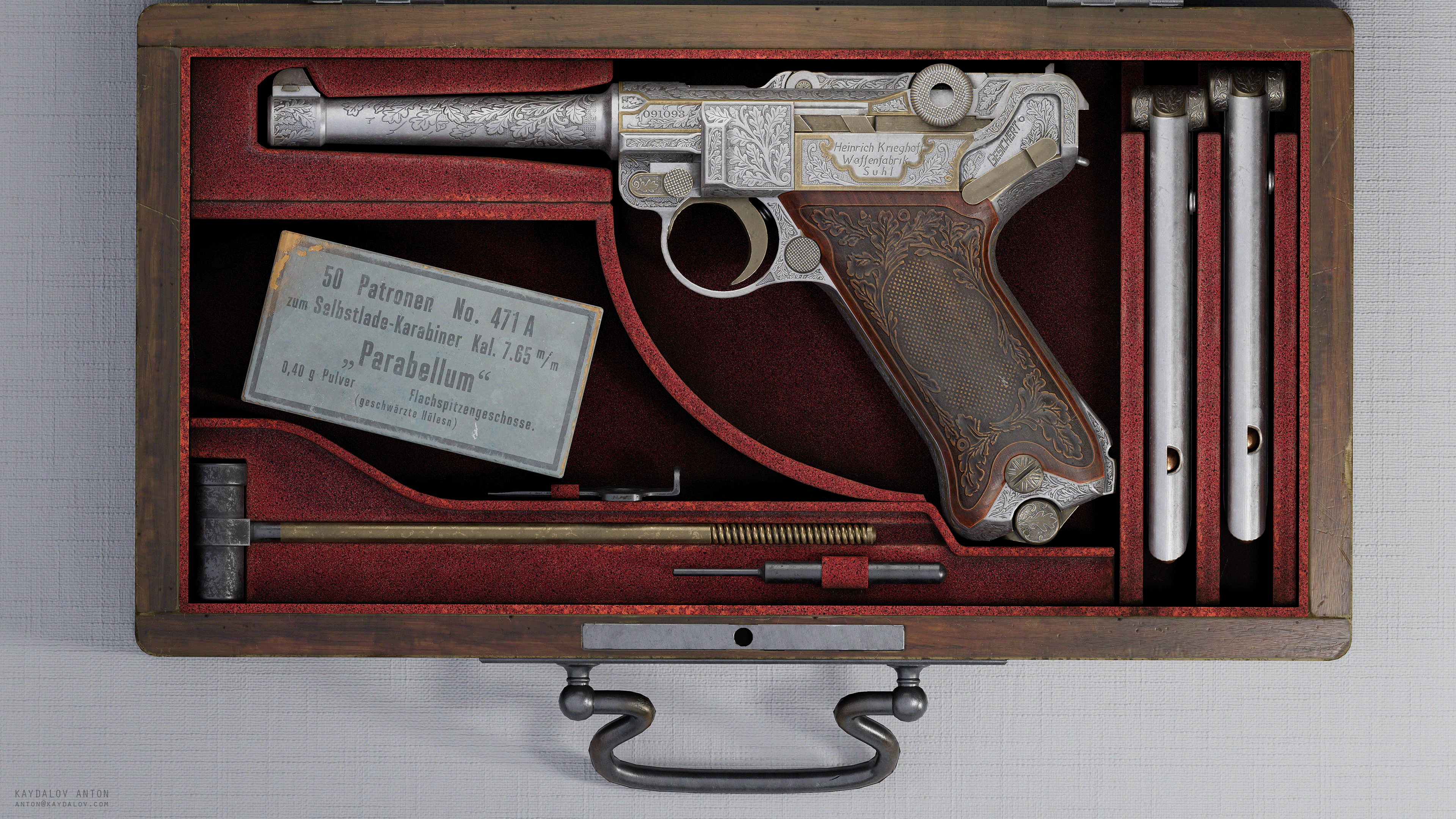
[Finished] Krieghoff Luger
Hello everyone!
I am very happy to show you my recent work. It was long and painful journey but I am super glad and happy to finish it! What most amazing is that I can finally show it!
This my personal project for practice and studying purpose. The main focus was to figure out how to do proper and good engraving. After 10 different method I did what you can see on screenshots. Also my practice goal was make all gun parts as possible.
The modeling part was done in Maya and Blender, texturing and whole engraving in Substance Painter.
I'll be glad for feedback and what do you think about it =)
More images here -- ArtStation - Krieghoff Luger, Anton Kaydalov


More images on art station page.
 kaydalord
Re: Texturing workflow technical help!
The difference in green channel value you are seing is probably coming from a confusion of terms.
"Bent" normals refers to a technique that fakes some extra shading by bending the normals in a way that is not just related to the surface of the high, but also to cavity information. That way when light shines down an object you get not only the shading based on the orientation of faces, but also some extra kick in the cracks.
https://docs.unrealengine.com/4.26/en-US/RenderingAndGraphics/Materials/BentNormalMaps/

Pretty neat stuff, especially since in UE4 an AO pass plugged into a material is ignored in many cases, as it requires a very specific setting in the level lighting settings to show up.
Now just like any normalmap bake, this special "bent" bake can be saved either as Tangent Space or as Object Space.
And then, there is the completely unrelated fact that an OS normalmap very cleanly isolates the up/down surface orientation of an object in its green channel.
So, the pass shown in the top right of the first image of that tutorial breakdown is not just a "bent normals" pass ; it's a bent normals pass saved as Object Space. But unfortunately for the sake of dumbed-down simplicity (and probably after some requests coming from artists who didn't understand what bent normals actually meant in the first place), some baking apps started calling this combined pass saved as OS a "Bent Normals pass", even though the part that most people are interested in is the top-down shading aspect of the OS bake, not the bent aspect.
And IIRC very ironically as @Neox pointed out, some baking apps even started to label "Bent Normals" an OS bake without even any bending whatsoever :D IMHO a perfect example of how "simplifying things for the user" just ends up causing confusions and errors. I am actually 99% sure that this is exactly what is going on in the tutorial breakdown.
Therefore, the pass from the tutorial (green channel of an OS-saved normals pass, probably without bending) will logically look very different from the green channel of an actual TS-saved bent normals pass, for two unrelated reasons.
(... and of course the difference you are getting could also come from somewhere else too :D )
 pior
pior