Best Of
Book of Tyrael
Hey gang! Long time no see.
I've been noodling with photorealism for some time now and decided to take on this old thing.
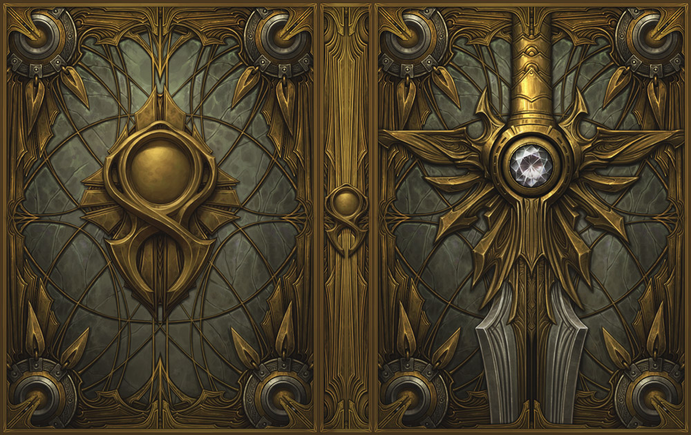
Naturally, as a modern day CG enjoyer, I went to town on that sweet sweet subdiv modeling. In Blender, no less.

With pretty shaders included!

I then tossed it over to Zbrush and effed it up a little, so that it looks properly old and beat up ^^ Just a little bit though.
And then over to retopology. This time in Maya, I haven't tried it in Blender yet, so in the interest on expediency I went back to my roots.

When all was said and done, I've sent it over to Substance and using a metric ton of macro references and another metric ton of coffee started texturing this bad boy!


So here's the thing, folks. I wanted to gauge your guys' opinion on how it's going so far. It's nowhere near done, there's still a lot of work to do, but i would really appreciate some feedack, if you got any.

Cheers!
 Svartberg
Re: AI Art, Good or Bad? A (hopefully) nuanced take on the subject.
This is hardly a good comparison.
The decent thing to do is to credit the asset maker, list what you used and most importantly, pay for the asset. Just like you paid for all the software in your pipeline. The artist also makes a choice of the assets to purchase. Amongst numerous other decisions, scene layout, converting materials, editing textures, lighting, rendering AOVs and compositing to realize the artwork.
These aren't rote tasks not needing creativity, they each require the thoughtful consideration and sometimes trial and error on the part of the artist. How many of these decisions are being made by the artist and how much of them by the AI when it comes to AI Art workflow?
Re: What Are You Working On? (3D) 2022
I finished this character base on concept art by Zatransis last week:

I've been meaning to post it here but it kept slipping my mind! More angles, progress shots, and a 3D viewer here.
 jgarrison
Re: AI Art, Good or Bad? A (hopefully) nuanced take on the subject.
I know that it feels wrong to you that AI looks at your images and then draws in your style. But feeling doesn't count. This part is simply not illegal. Style cannot be patented. Maybe in the future there is some regulation. But not now.
Well I mean, it sort of counts. You seem to have this interesting viewpoint that it doesn't matter if it isn't strictly (at this point in time) illegal.
But like...
Being an asshole isn't illegal. But if I can help it, I'm still not going to associate with, hire, or financially contribute to the livelihood of assholes.
There's a lot of things that aren't illegal that don't make the world richer. Making it easier for stupid people to be stupid and disrespectful isn't an impressive innovation. Creating tools that encourage corporate greed, that push people to keep consuming, that tell people results come not from well-meaning effort and study but from ripping people off - this does not benefit mankind (or local community, or even oneself).
Why is it we started with stealing from artists? Why did we instantly try - all over the world, to monetize people being lazier? To reward people who do less work, who have less creativity, and harm those who are already a rare and valuable breed of person? We seriously thought that was better than training AI to detect cancers? We want to put out apps on Google Play more than we want help designing better prosthetics? Solve for energy efficiency?
Of course we do. Like with most other things, it's easier to do harm than it is to do good. And as this technology perfectly illustrates (lol) - people want to be lazy.
And yes - as you've pointed out @Tiles - there are many technological innovations we've had and use that make people lazier. This is not the first. It's becoming more and more clear that we've been foolishly chasing some truly stupid things for a good long while. I hope that the world pivots, regulates, and brings things to a more reasonable and respectful place with regards to AI generative content. I hope that we wind up in a place where people like you can be happy, and the artists of the world can feel respected at the same time.
Until then - as you've noted, you are allowed to go about doing what you're doing. For all intents and purposes at the moment, it is not "illegal". And similar to how respect for the artists whose work was used was apparently not required...
Respect for the people who use the tools is also, not required.
 Two Listen
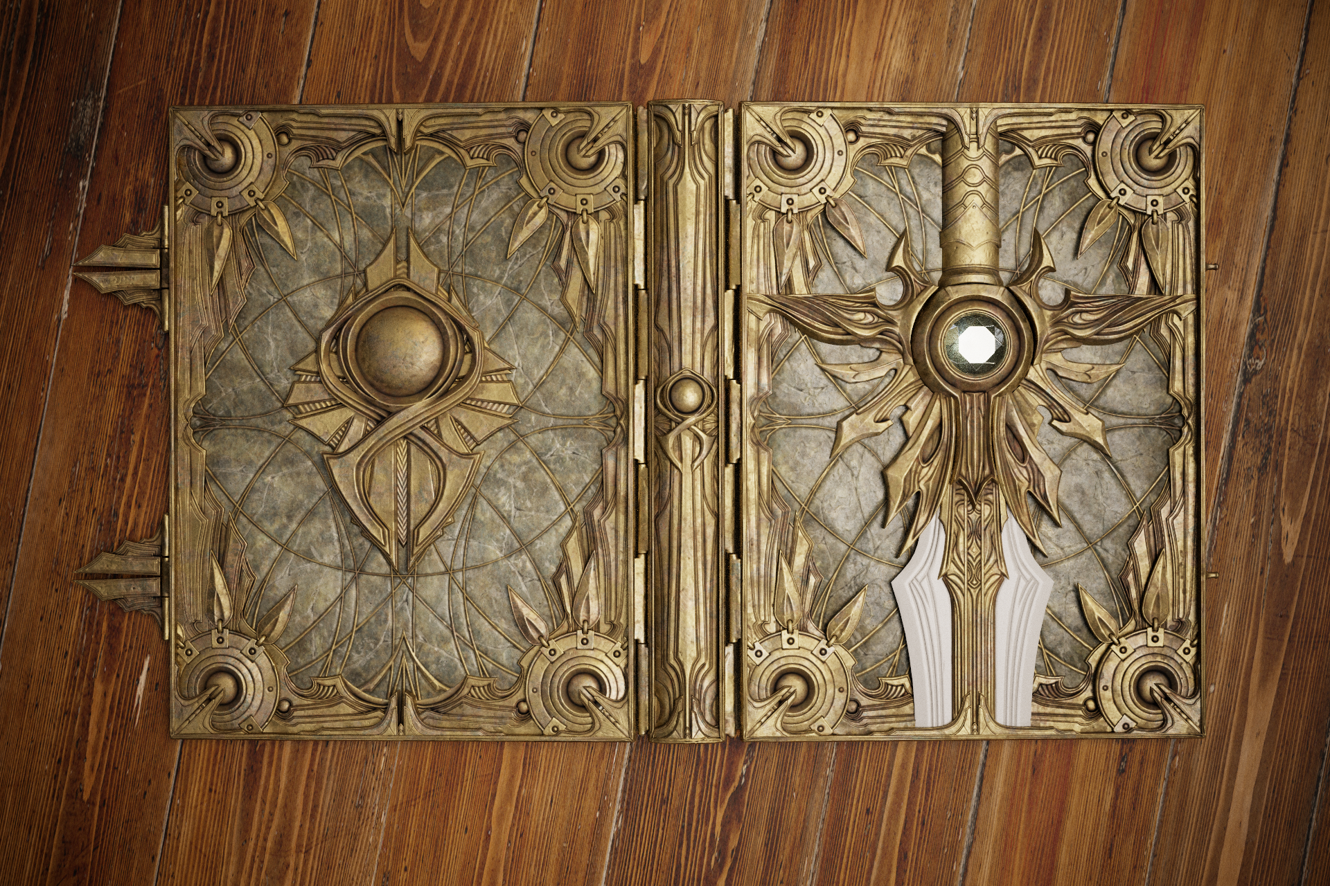
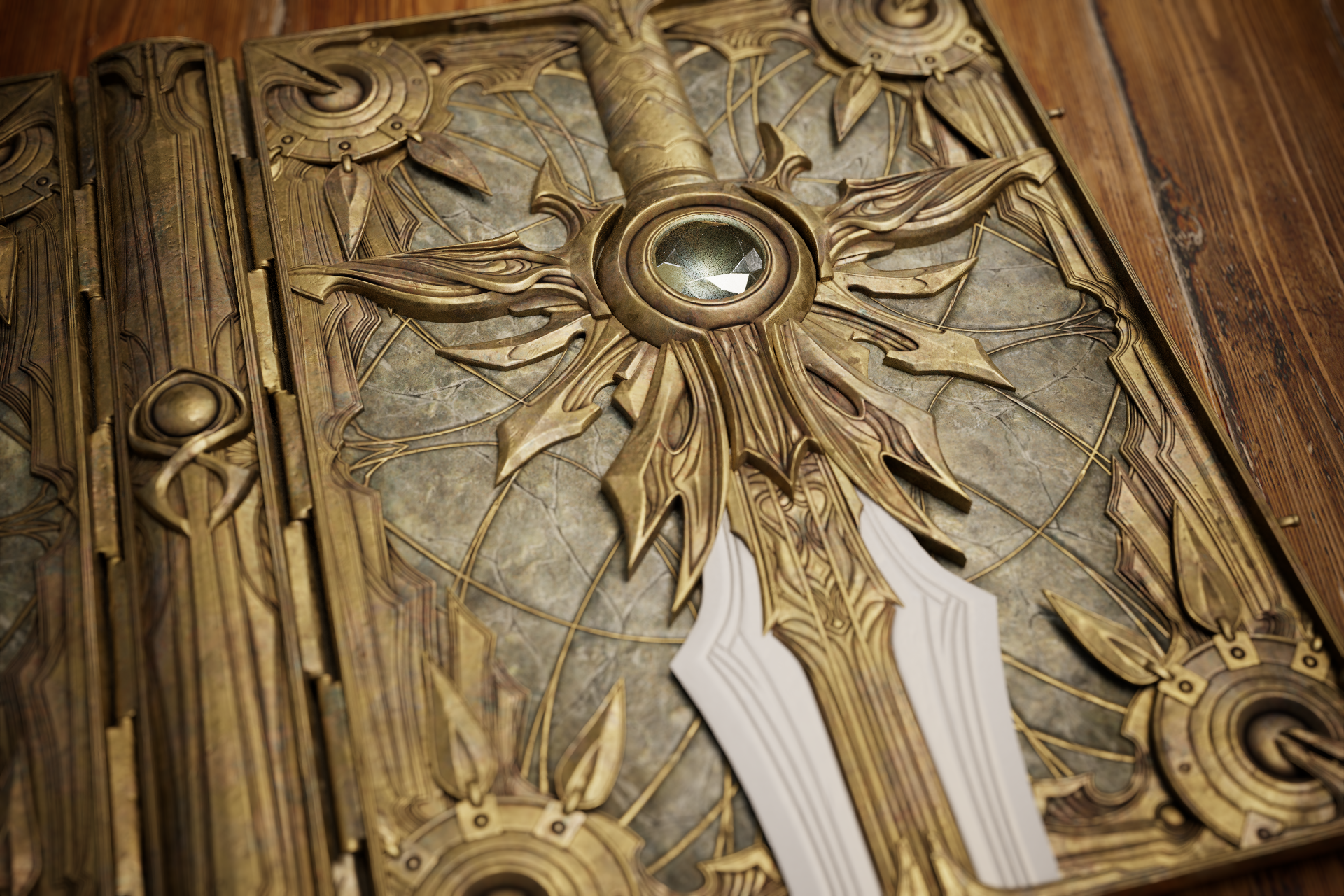
Re: Book of Tyrael
Thank you so much guys. You're totally right about the metal and the feather-like elements. I also did some work on the white metal.
Still need to do some experimenting with a diamond and then move on to paper.

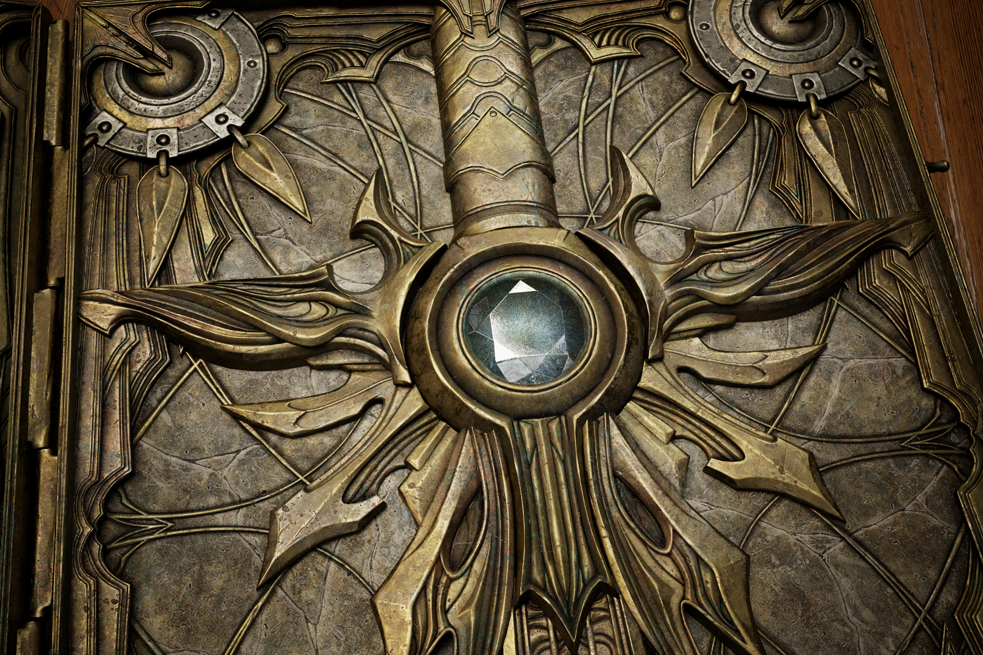

Also, raytracing was eating up some AO so I painted some to add the accents on the layered parts. Maybe it got a little out of hand, let me know what you guys think.
 Svartberg
Re: AI Art, Good or Bad? A (hopefully) nuanced take on the subject.
What a well-needed Xmas break ! I hope all of you managed to take a bit of a breather and enjoy friends and family (all that while AI-children were probably busy feverously typing into the MJ server to get the most out of their paid sub by the end of the month)
There's still a ton more to unpack though (probably for later).As far as I am concerned the only 2 ways I found to not think about all this are : spending time with close relatives/friends, and pouring even more hours into meat-made-art (even though I have no idea on how we will resume sharing pictures online again from here on). Even the most mundane things become precious, from manual retopo and UVs, to ... crocheting. Or rather, watching someone crochet, because come on :D
Also, outside of the legal battles and the inevitable upcoming regulation on image data sniffing, I feel like there's the possibility of a backlash from the general public. I was pleasantly surprised to see some of the comments under a LensaAI selfie that Megan Fox uploaded, with her followers quick to point the art theft issue. The genie may be out of the bottle, but the cat is out of the bag too. I think AI-cunts don't realize that by targeting art they are attacking something that many, many people actually understand and cherish.
The tech still has incredibly dark consequences though. Knowing that there is a bunch of AI-morons out there rejoicing at the idea of instant-xeroxing artists for their own little daily dopamine rush and/or to hopefully make a quick buck is incredibly unsettling.
Anyways ! Got some therapeutic retopo and pencil wiggling to do :)
 pior
pior
Re: What Are You Working On? (3D) 2022

more on my '71 chevelle - mixture of booleans and manual hole cutting
got the actual chevelle type face( more or less)
car paint shader by Guilherme Campos
 Ruz
Ruz


Re: Is there a protest going on right now at Artstation?
Hi there @Alex_J
I honestly don't have a well-formed answer to all these valid points - I just know that trust really is the cornerstone of all prized relationships - be it with family, friends, and in business.
And indeed trust only comes with time, but even here on an online forum (a form of communication that many probably find obsolete compared to the speed and bandwidth of current social media) I'd bet that many users can point out who they would trust for career advice for instance - merely based on post history and past online public interactions, all that in basic text form. So even though things aren't always clear cut and building relationships does take time, I do believe this is possible. Of course I can only comment from my own perspective, but even students or self-taught enthusiasts just starting out can quickly form relationships through working together on various projects for instance. As long as other similar-minded people still have the will to work on art projects at all to begin with, that is ...
(On a side note, this is precisely why the use of NFT in art transactions immediately raised red flags for me - because IMHO the last thing one needs between an artists and their audience or clients is some layer of tech attempting to prove authentication. As that literally means that neither party trusts the other.
As for the scope of so-called "online communities" shrinking back down ... Well, I personally don't really have a problem with that really, as one doesn't need an infinite number of online acquaintances in order to feel a sense of belonging to a group of people sharing a common interest.
pior
Re: AI Art, Good or Bad? A (hopefully) nuanced take on the subject.
I must say that I am now genuinely torn between two very conflicting states :
• On one hand the combative spirit is a powerful driver, and the rollercoaster of the last few days/weeks put a lot of incredibly important things in sharp perspective : how one expresses oneself through their craft as imperfect as it may be, and how it is possible to retrace the whole life of a person through the marks they left. This is imho truly beautiful stuff, especially in contrast to incredibly polished "/beautiful woman, /big breasts, /sunset, /4k, /8k, /realistic, /superrealistic, /in the style of xxx, /trending on yyy" AI vomit. Even the small mistakes sometimes made by master craftsmen become suddenly more beautiful than ever in my eyes. Seriously : Frazzetta posters, Bilal and Moebius comics pages, Miyazaki storyboards, and of course Kim Jung Gi madlad murals are real tear jerkers now because of how beautifully imperfect their art is in many ways.
• However ... on the other hand the complete disregard to the love that artists put into their craft (as expressed by the incredible toxicity of AI bros, the deafening silence of Artstation/Epic, and the way the masses splurge on LensaAi (including tech "influencers" who should really know better) is just an incredibly heavy weight to carry and that's really new. I of course understand that people who never had the desire (and from there the opportunity) to be involved in a creative field are unlikely to know the feeling of rolling up their sleeves to tackle a seemingly huge task as a team and eventually getting it done ; so I can't blame them for not knowing that the biggest motivator is knowing that someone out there will appreciate the result. But now that there is an audience absolutely ready to consume (and generate) bot-made content at breakneck speeds thanks to an unethically trained model, I feel like the incentive for artists to work on entertainment properties will take a nosedive. Why put in the hard work, if a massive part of the audience doesn't actually care that someone did it ? This is now impossible to blissfully Ignore.
- - - - -
I also feel like it will be harder than ever for younger artists to gather the strength to self-improve and attempt to reach the heights of the masters they look up to when knowing full well that someone, somewhere is gleefully typing up prompts to generate pictures straight up emulating that one fragile thing they cherish. Of course that doesn't prevent anyone from picking up a pencil, but the mental background noise to filter out is pretty damn massive. This simply wasn't there before and this is very invasive in many ways.
Same for seasoned pros : I just can't imagine Miyazaki gathering up strength to design/direct another movie after witnessing people gleefully generating facsimiles of his art at the click of a button (because of course "in the style of Ghibli" is a popular prompt).
On the plus side, perhaps the sometimes challenging and tedious aspects of "human" art will become something to cherish more than ever. But for it to be even possible, one still needs to put a roof over ones head first ...
- - - - -
Lastly another somewhat related shower thought : Now that AS/Epic crapped the bed, artists from all over the entertainment industry have a permanent grudge against them. How can this possibly be reconciled with the massive market penetration of Unreal Engine in games and now TV and movies as well ? Sure enough there's a irreconcilable personal conflict there for anyone working at a studio commercially tied to UE. Or (sigh ...) producing marketplace assets.
pior