The BRAWL² Tournament Challenge has been announced!
It starts May 12, and ends Sept 12. Let's see what you got!
https://polycount.com/discussion/237047/the-brawl²-tournament
It starts May 12, and ends Sept 12. Let's see what you got!
https://polycount.com/discussion/237047/the-brawl²-tournament
Best Of
Re: How The F*#% Do I Model This? - Reply for help with specific shapes - (Post attempt before asking)
@Veer_P Not a problem. Like @sacboi pointed out, subdivision modeling tends to be an iterative process and there's a few different ways to establish the basic building blocks that define the shapes. The modeling approach used to create the very first shape in the
previous example is usually called edge extrusion or point inflation
style modeling.
Which approach you use to model those basic shapes really comes down to personal preference and the tool set available in your application.
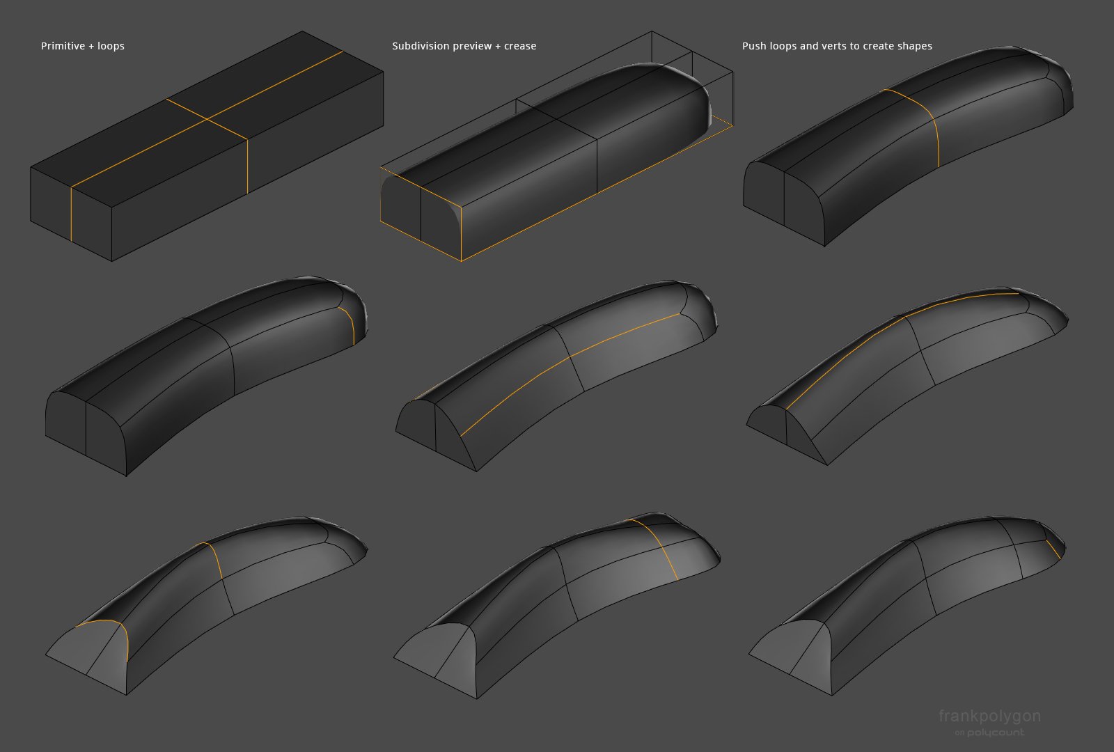
Box modeling process: insert a cube and adjust the dimensions until it creates a rough bounding box around the shape. Add some loops down the middle of the rectangle then add a subdivision modifier and enable subdivision preview. Select the edges that define the bottom and back of the shape then apply a crease to limit the smoothing. Scale and move the edge loops until the basic curvature is formed from the top view then start adjusting the position of individual edges and vertices to refine the curvature in 3D space. Add a loop cut near the front to constrain the hemispherical shape fall off there. Push and pull the N pole verts at the front to adjust the height and curvature.
It may also be worth looking some older, application specific, subdivision modeling videos on YouTube to see the fundamentals and individual modeling operations in action.
Addendum: made a couple of minor edits in the contemporary workflow description to soften the language around the reduced prominence of subdivision modeling in game art workflows. Subdivision modeling can still be relevant for game art. It's just that for certain things it's not time efficient when compared to other sculpting and parametric modeling workflows.
This is especially true when talking about pure subdivision modeling that relies almost exclusively on manual editing operations. Hybrid subdivision workflows that leverage booleans, creases, and modifiers are much more time efficient (if not competitive) and can produce lightweight models with high quality surfaces for baking and rendering. The primary downside is the learning curve is a bit steeper than some contemporary workflows.
Which approach you use to model those basic shapes really comes down to personal preference and the tool set available in your application.
This is going to be a bit of a tangent but after thinking about it for a minute, it kind of seems like a lot of the fundamentals (especially the terms) aren't talked about in detail all that much anymore and a lot of the resources that many of us older artists learned on are long, long gone. (Though here's an old thread from 2006 comparing box modeling to strip modeling.) Even searching here on the Polycount forums, it seems like there isn't all that much discussion about some of these fundamental concepts and the niche terms we used to use to describe them.
Which makes sense because most artists probably came here after learning the basics of modeling somewhere else. There used to be a bunch of websites / forums dedicated specifically to
subdivision modeling and a lot of the discussions there covered
different ways to approach pure subdivision modeling for everything from
non-living organics to detailed human anatomy to hard surface objects.
There's probably some video tutorials or even older text tutorials that
explain the different modeling styles. A lot of subject specific
workflows have evolved to use dedicated applications (E.g. organics, characters, and
creatures are mostly sculpted, clothing and soft goods are often
simulated, hard surface is increasingly done with boolean remeshing or
parametric modeling, etc.) and pure subdivision modeling isn't the primary go
to, do all that it used to be and quite frankly it hasn't been for some
time. At least not in game art.
[Though there still are some areas where it's relevant or useful.]
[Though there still are some areas where it's relevant or useful.]
This is by no means an exhaustive description or list of subdivision modeling philosophies but some of the more common approaches are:
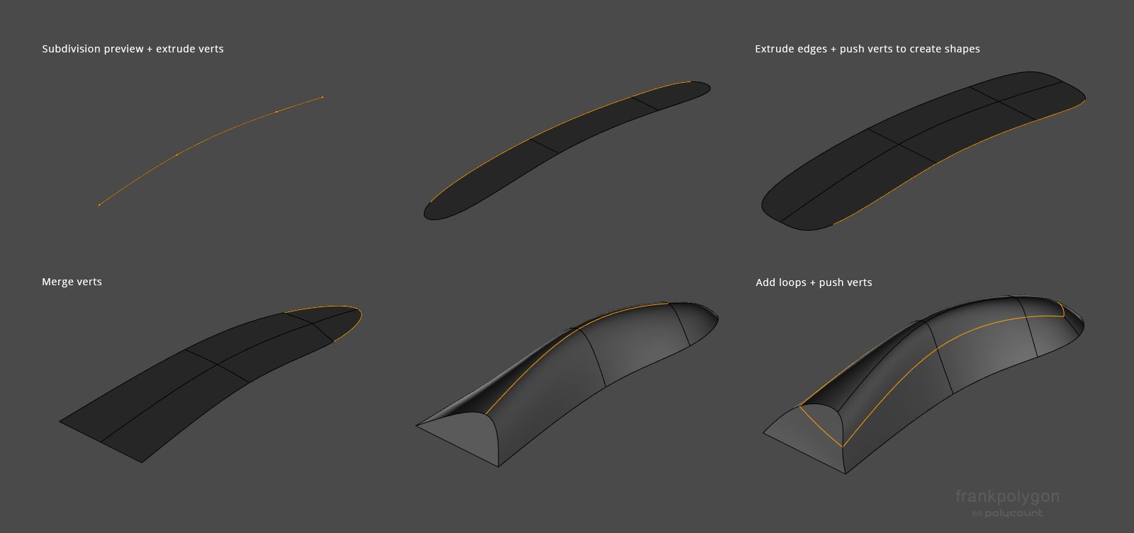
Edge extrusion / point inflation modeling process: Start with either a flat primitive and extrude the edges into shape or extrude a sting of vertices that follow the basic curvature of the shape. Extrude the edges outward to create the shape profile then merge the center vertex at the end to bring everything to a sharper point. Push the vertices of the center edge up to loft the shape then add a loop cut to control the curvature on either side and push the edges / verts around until the basic curvature matches what's in the reference images. Everything here is done with the subdivision preview enabled, so use creases to control the edge transitions at the back of the shape.- Box modeling (Subdividing, manually manipulating and merging primitive shapes to create complex forms.)
- Edge extrusion modeling (Extruding edges in 3D space then connecting and adjusting them to create complex forms.)
- Point inflation modeling (Extruding a string of vertices along a 2D plane then rotating or pushing them into 3D space and connecting the adjacent edges to create complex forms.)
- Strip modeling (Extruding a line of quads to create shape profiles then connecting them with a quad grid fill to create complex forms.)
- Boolean modeling (Using tools to generate primitive and complex shapes that are automatically combined into more complex forms.)
Each of these approaches has it's own strengths and weaknesses, so they tend to be used more for one specific type of modeling. E.g. box modeling naturally forces quad grid topology and requires capturing the larger shapes first before applying the next level of subdivision and doing a detail pass so it tended to be used more with organics and cartoon style characters. Edge extrusion modeling and strip modeling provided a greater level of control over geometry density and topology flow but it required more planning and experience so it tended to be more useful for complex characters, clothing, and 'semi-organic' hard surface subjects like vehicles.
Point inflation modeling was kind of an offshoot of edge extrusion only instead of using edges it was individual vertices. Boolean modeling was something of a bridge from subdivision modeling to the re-meshing workflows that took over hard surface. It leveraged the flexibility of more advanced modifier based tool sets to allow for non-destructive block outs and semi-automated support loop placement on very complex surfaces.
Point inflation modeling was kind of an offshoot of edge extrusion only instead of using edges it was individual vertices. Boolean modeling was something of a bridge from subdivision modeling to the re-meshing workflows that took over hard surface. It leveraged the flexibility of more advanced modifier based tool sets to allow for non-destructive block outs and semi-automated support loop placement on very complex surfaces.
Most of the actual modeling operations in 3D DCCs can be applied to each style of modeling and there's some overlap between the different approaches. Which is why these definitions are pretty basic. Another rabbit hole is "loose Vs strict" modeling and topology layout strategies. [One of the reasons any of this is still relevant is: learning about poly and subdivision modeling helps build transferable fundamental skills like artistic observation, problem solving, order of operations planning, shape recognition, mesh optimization, etc. by practicing processes that provide direct feedback.]
Here's a brief visual overview of the typical edge extrusion and box modeling approaches to the basic shapes of the part in question.
Here's a brief visual overview of the typical edge extrusion and box modeling approaches to the basic shapes of the part in question.
Box modeling process: insert a cube and adjust the dimensions until it creates a rough bounding box around the shape. Add some loops down the middle of the rectangle then add a subdivision modifier and enable subdivision preview. Select the edges that define the bottom and back of the shape then apply a crease to limit the smoothing. Scale and move the edge loops until the basic curvature is formed from the top view then start adjusting the position of individual edges and vertices to refine the curvature in 3D space. Add a loop cut near the front to constrain the hemispherical shape fall off there. Push and pull the N pole verts at the front to adjust the height and curvature.
It may also be worth looking some older, application specific, subdivision modeling videos on YouTube to see the fundamentals and individual modeling operations in action.
Addendum: made a couple of minor edits in the contemporary workflow description to soften the language around the reduced prominence of subdivision modeling in game art workflows. Subdivision modeling can still be relevant for game art. It's just that for certain things it's not time efficient when compared to other sculpting and parametric modeling workflows.
This is especially true when talking about pure subdivision modeling that relies almost exclusively on manual editing operations. Hybrid subdivision workflows that leverage booleans, creases, and modifiers are much more time efficient (if not competitive) and can produce lightweight models with high quality surfaces for baking and rendering. The primary downside is the learning curve is a bit steeper than some contemporary workflows.
3 ·
Re: Show your hand painted stuff, pls!
Beautiful work on the glass! I feel like the cloth could be softer tho, too bold AO i guess, feels nowhere near as refined as the glass
3 ·


Jaipur Palace Door


This project was created mainly to practice making trimsheets as well as creating something that looks nice and inspires me , after a lot of research my pick was Jaipur city palace door , i wanted to make only 1 trimsheet that includes as many details as possible to see what i can build with it , i started modeling the door and once i planned the Uv area it would take half of the texture was empty so i kept adding more assets till it was filled that include the door frame and these marble decorations on the side as well as the floor, I am glad i was able to achieve this result for first try but still there is always a room to improve , hope you like it & Critiques are always welcome .
for more breakdown :
https://www.artstation.com/artwork/dyB1XW
4 ·
Re: The Bi-Monthly Environment Art Challenge | July - August (97)
Hey, I'm not taking part myself as I'm busy with another project  but I like the HS prop and figured I might share my thoughts on in with others.
As the concept seems very basic and has a lot of blank spaces it looks like a nice opportunity to approach it in creative way and build one's own ideas on top. I'd try adding some elements that would follow the function of the device - conisder foldable legs within black bottom part (might be interesting if they overlap the middle section), a handle for picking it up(it could be a reccess not to change silhouette), control panels, plugs, diodes etc. Look up pictures of how similiar devices are used to better understand what placement of elements would be convenient") Hope this helps
Hope this helps

@Arahnoid if you're using blender I'd suggest to try using modifiers for non destructive modelling in such cases, you just need bevel controlled by weight that you can adjust per edge and weighted normals so that you can keep your editable wireframe simple

As the concept seems very basic and has a lot of blank spaces it looks like a nice opportunity to approach it in creative way and build one's own ideas on top. I'd try adding some elements that would follow the function of the device - conisder foldable legs within black bottom part (might be interesting if they overlap the middle section), a handle for picking it up(it could be a reccess not to change silhouette), control panels, plugs, diodes etc. Look up pictures of how similiar devices are used to better understand what placement of elements would be convenient
@Arahnoid if you're using blender I'd suggest to try using modifiers for non destructive modelling in such cases, you just need bevel controlled by weight that you can adjust per edge and weighted normals so that you can keep your editable wireframe simple
3 ·
Re: The Bi-Monthly Environment Art Challenge | July - August (97)
i decided to make the stylised prop model, i couldnt figure out lighting for the hardsurface one. the texture painting in blender was very fun to make

5 ·
Re: The Bi-Monthly Environment Art Challenge | July - August (97)
Cool stuff! although the mechanism seems to me to be overly intrusive as you need to lift the whole lightsource to reach buttons, a practical solution that comes to mind would be foldable screens in cameras 
3 ·
Re: [Baking Error] Having Hard Seam Line
Hi! Props for attaching files :-B

Taking a look at the lowpoly, I'd say with beveled edges and the resulting mesh shading, hard edges become redundant. While hard edges need UV splits (when baking a normal map), not every edge along a UV split needs to be shaded hard. I would use use hard edges deliberately in places where it meaningfully removes gradients from mesh shading, like steep angles.
Then, I recommend straightening the UV islands to not have aliasing artifacts along seams. When not using hard edges, you can have fewer seams in areas where they're less noticeable.
I also think that texel density is too low here. To address that, you could
A - increase texture resolution
B - texture by mapping UVs to an trim atlas
C - assemble the crate from a couple detailed board modules
or perhaps it's a combination of those options. And likely there's more
Keep it up
 Fabi_G
4 ·
Re: [WIP] Triumph Rocket 3R Bike (SubD Model)
More parts. Will probably revisit those pieces and fix some minor shading and topology issues


 kosh3d
3 ·