Best Of
Re: Game Industry Layoffs - WTF?
You know what?
Now.
Now is the time to go all in on gamedev. Game developers make their own fate.
When life gives you Savathûn, don't make lemonade! Make life take the Tyranids back! Get mad! May CHAOS take the world!! I don't want your damn Skooma! What am I supposed to do with these? Have sex with a bear?!
Stolen breastmilk is the mindkiller! Make life rue the day it thought it could give the Elden Lord lemons! Do you know who I am? I'm the lyin' khajiit whose gonna burn your orc statue down... with the lemons!!
 zetheros
3 ·
Re: Game Industry Layoffs - WTF?
I've been laid off several times - when it happens the best thing to do is go and get another job.
Blaming society/corpos/the man for your problems is fun but you can't exchange self-righteous indignation for goods or services in most places so it's ultimately kinda pointless.
Blaming society/corpos/the man for your problems is fun but you can't exchange self-righteous indignation for goods or services in most places so it's ultimately kinda pointless.
3 ·
Nissan VR38DETT Engine
Hello,
I have been working on this engine for a car project. The engine is almost there so i wanted to show it off a little. Its based on the R35 GTR engine but isn't strictly a copy. All modeling is being done in 3Ds Max and rending is in Redshift.


I have been working on this engine for a car project. The engine is almost there so i wanted to show it off a little. Its based on the R35 GTR engine but isn't strictly a copy. All modeling is being done in 3Ds Max and rending is in Redshift.
 jaker3278
5 ·
Re: How to reduce normal map baking artifacts caused by low/high poly mismatch?
Made a tutorial just for this specific case for new comers, also shameless promotion 
https://www.artstation.com/artwork/rlGqrE
https://www.artstation.com/artwork/rlGqrE
 HAWK12HT
3 ·
Re: Game Industry Layoffs - WTF?
Maybe the game industry turned into a zombie while we weren't looking and now it's not the person we once loved. Mercy might be the only option.
Maybe (probably) it will be reborn because - like books and movies - it is still needed, it is still important. Sure it probably won't be near quadruple-A budgets (itself a red-flag concept the moment it was first suggested) or planet-sized audiences. But maybe it will become healthier. Find its true form eventually.
Maybe there is hope, if not in the way we expect.
Of course, it probably won't be any consolation to people who have lost or will soon lose their jobs.
I hope everyone affected will somehow land on their feet and find the way again. I hope studios will find a way to thrive in independence or under new management.
 stray
stray
4 ·
Re: What Are You Working On? (3D) 2026
ArtStation - 《空山寂寂松声远》, F.Y.Z 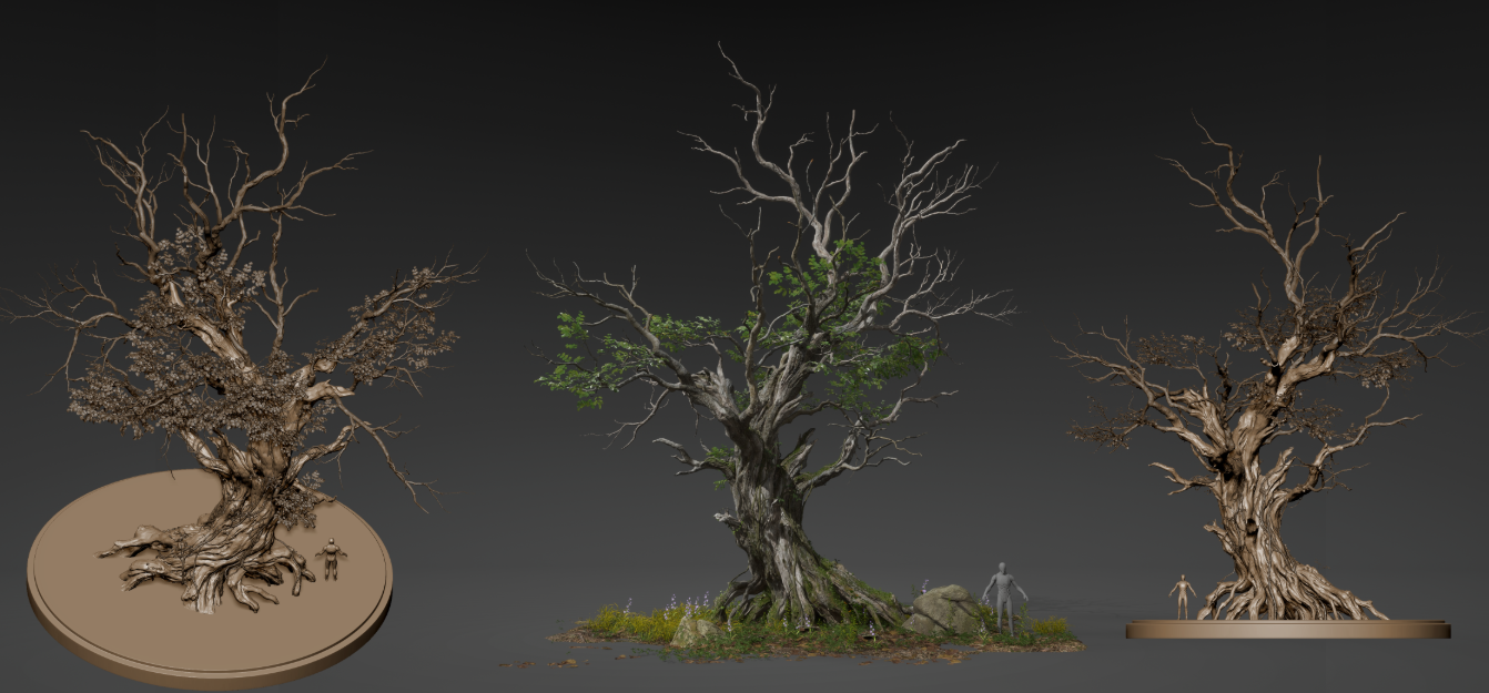 This is a personal project of mine, with a heavy focus on mastering foliage and vegetation creation.
This is a personal project of mine, with a heavy focus on mastering foliage and vegetation creation.3 ·
Re: Airborn Studios: Project Dragon Art Blast - Very Image Heavy!
Misc Furniture & Props :


NPC Homes:


Parallel Dimension:


Plains Biome:


Purran Furniture & Props:


Purran Wagons:


Ruins:


Spooky Forest Biome:


Spooky Forest Props:


Start Screen:


Valekin Architecture:


Valekin Furniture & Props:


VFX:


Wyvarr Architecture:


 Wyvarr Furniture & Props:


Damn you made it this far! 2d is over now, lets roll into the 3d reals shall we?
5 ·
Sketching & Finished work
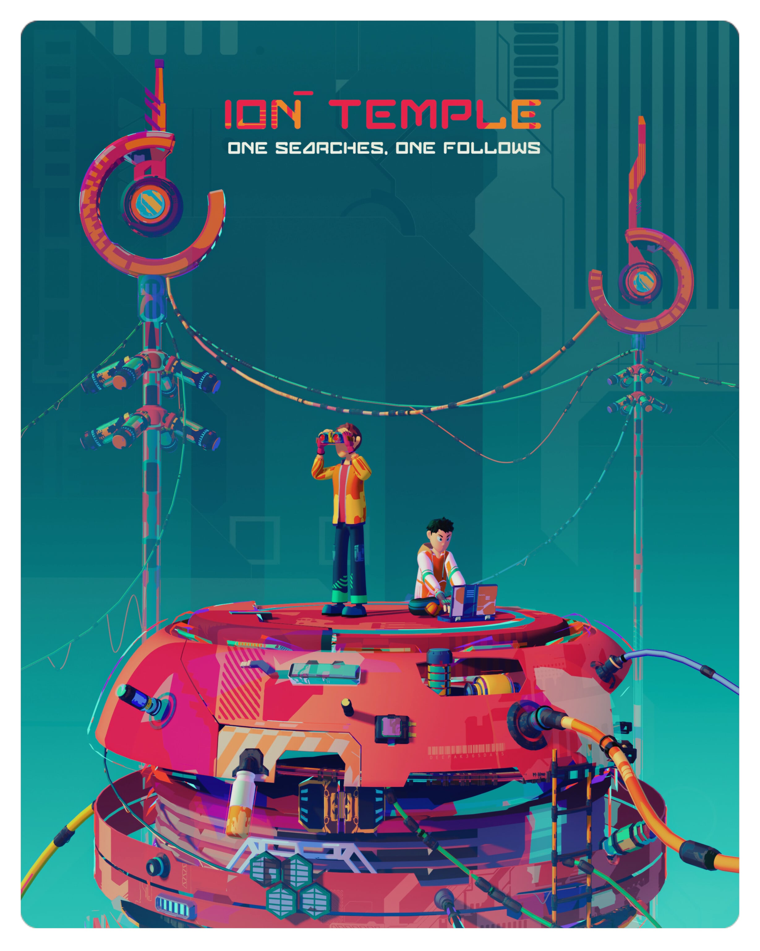
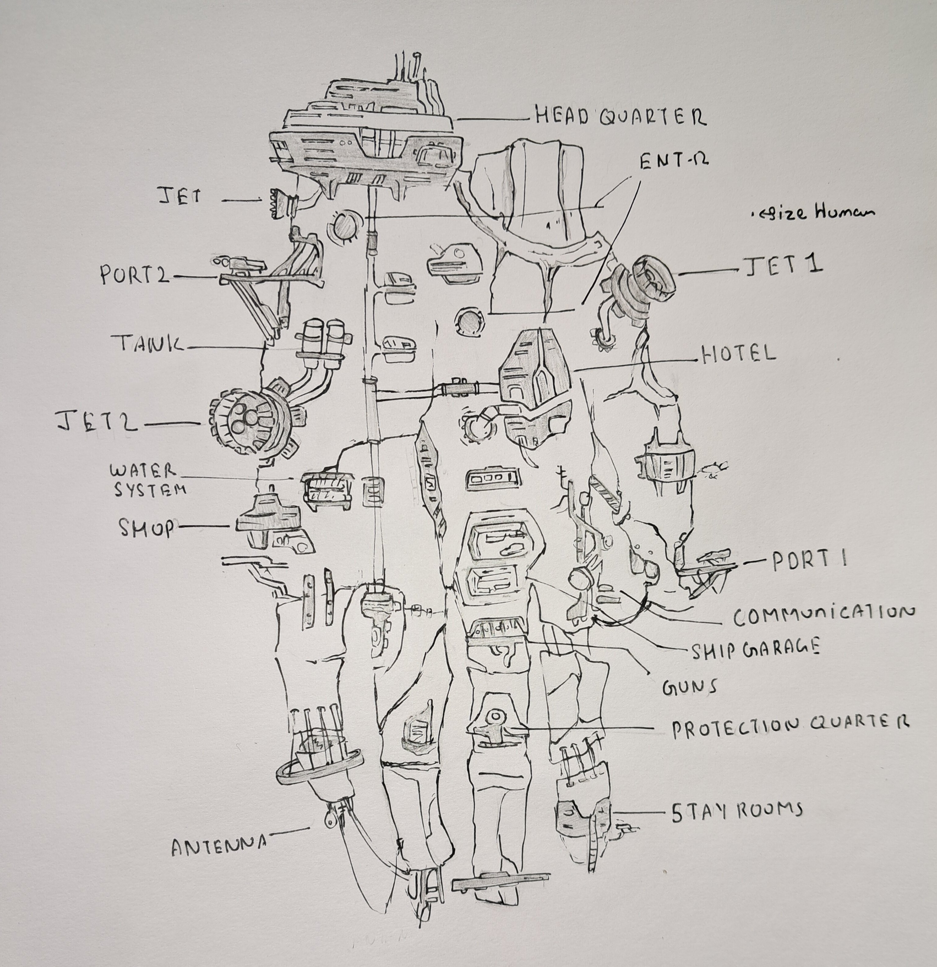
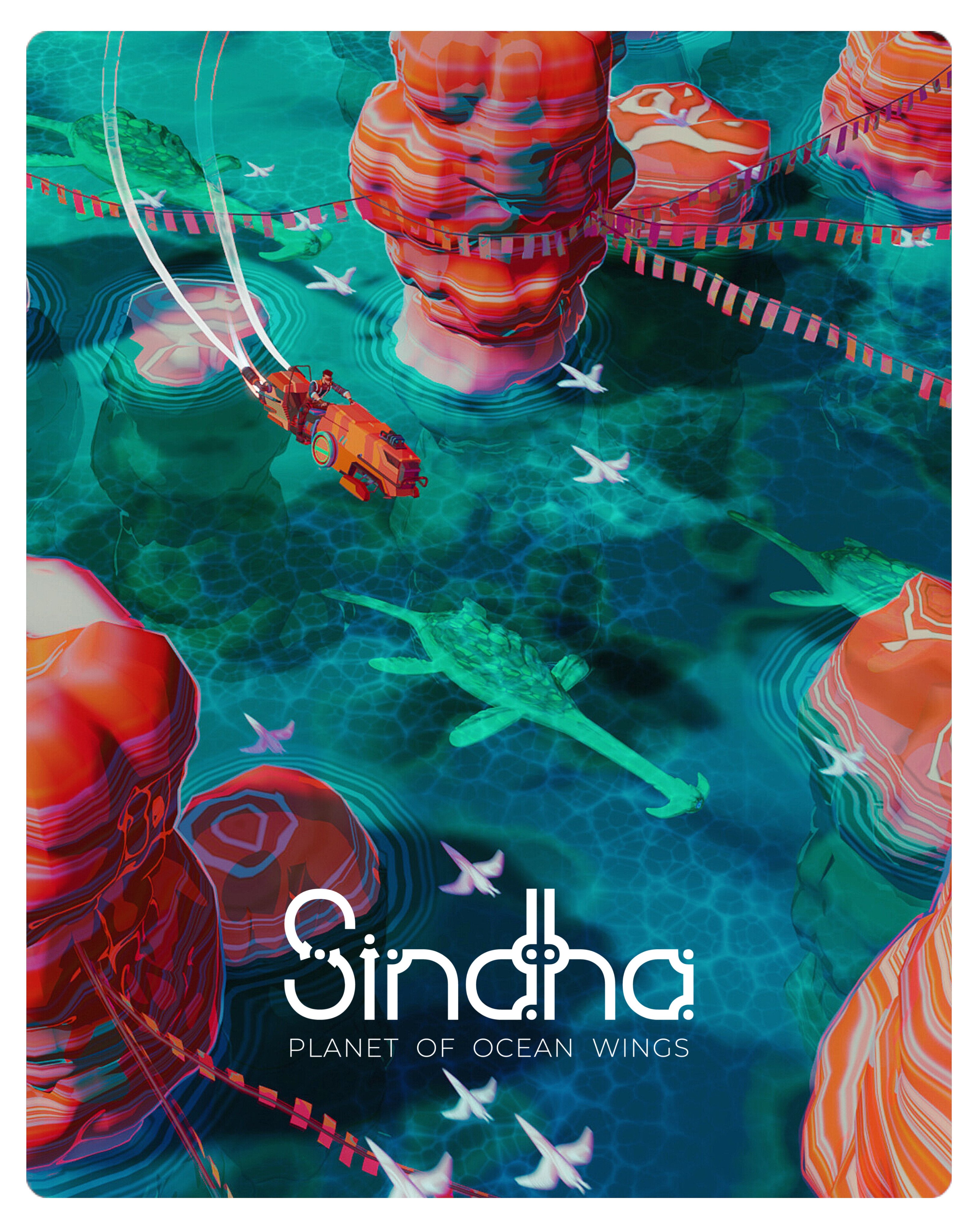
These are some of my original artworks which I worked in this year.
I made them in Blender 3d, with stylized look and specially towards high saturated color pallet.
These are more like my personal projects and exploration to find some style.
Steps involved in making these:
1. References searching
2. Sketching and mixing different ideas etc, to have something to start
3. Modeling, sculpting, rigging and making necessary assets ready.
4. Composition.
5. Texturing and lighting .
6. Rendering and color corrections.
 deepak365days
3 ·
Re: The Bi-Monthly Environment Art Challenge | July - August (103)
This is my blockout so far

 Pep_mepla
5 ·

