Home Technical Talk

Trimsheet normals inverted when rotating UV islands

polycounter lvl 3
Offline / Send Message
TheSteamDyer polycounter lvl 3
I find myself stuck with a mistery that is making me loose hours of work without any progress whatsoever figuring it out.
I'm making a modular environment and I'm making some trimsheet textures. In this specific case let's take a door frame made of three pieces (two vertical, one horizontal on top. Everyting is cool and neat until I take a vertical face and rotate it in the UVs to match it to the horizontal trimsheet, and that's when the normal map appears inverted in my scene. The trims were baked with substance painter, the modelling and unwrapping is done in Blender, the final result needs to go to Unreal. Funny thing, if I flip the face normal it appears correct (but then I have a flipped face obviously).
I don't understand why this is happening nor how to fix it, I tried pretty much everything that came to my mind. If I rotate the UV island to be vertical the normals appear correct, but then it doesn't match the trimsheet anymore.
Here's a pic to describe the problem:
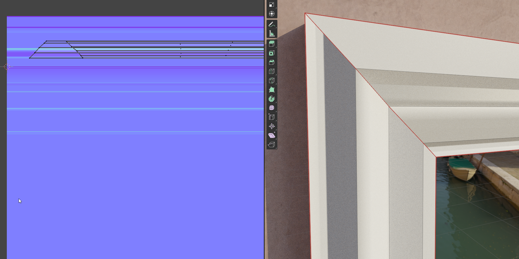
Here you can see the UVs of the frame on the left (they are overlapped to match) and the actual result on the right. The seam is in corner and it's evident that the normals don't match. This happens in Blender, but in Unreal I get the same result.
I also tried with a new geometry and this is the result:
if it's flat on the ground it looks correct...
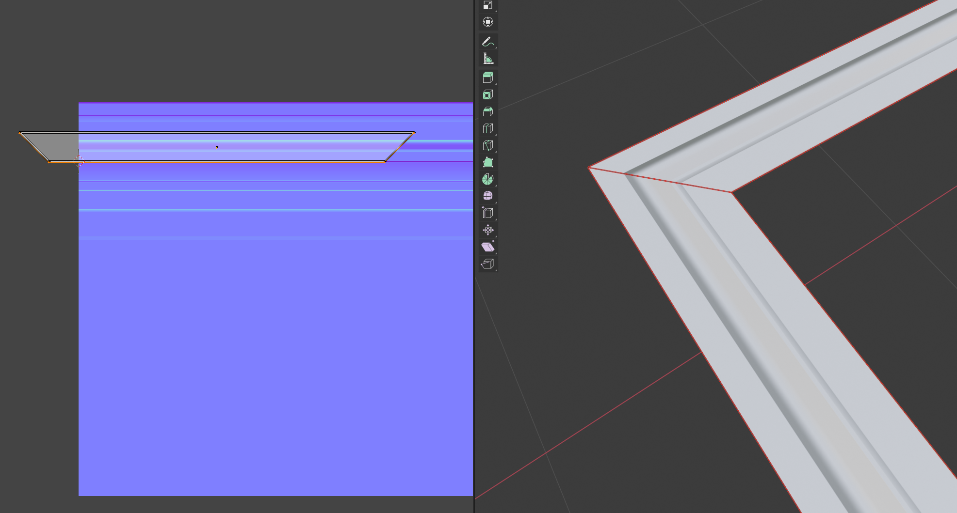
but if I rotate it 90deg on the x axis so that it's standing like the door, inverted normals :D

Can we agree this doesn't make any sense? Or am I missing something?
To be clear: there are no flipped normals, I also recalculated them multiple times, no split normals or custom normals of any kind, the normal map was baked for DirectX but doing it for OpenGL didn't change anything, and as far as I know Painter bakes in Mikkt, in the material nothing is going on (I can confirm that because in Unreal I only plugged the normal map in the normal input at it gives the same result) and the color space is correct (no sRGB). The geometry is not the problem since as I showed I tried with a plane where I just insetted the only face it had and deleted the center. Maybe it's something with Blender? I couldn't try in other softwares like max or maya since I don't own a license.

If you read all of that thank you, finding someone with more experience that can help me figure out the problem is the only card I've left.

Replies

  • wirrexx
    Offline / Send Message
    wirrexx ngon master
    Maybe your uv is flipped? flip it and see if it works.

  • DavidCruz
    Offline / Send Message
    DavidCruz interpolator
    i'll try to add another possibility I've run into on any 3d models, reset X form (in max idk what it is in blender) and maybe double faces on that location ? I've had this its not fun.  Hope you figure it out, glad you did the flip normal cause it was my 1st thought, since it looks simple enough i'd just redo it, probably much faster than waiting.
  • TheSteamDyer
    Offline / Send Message
    TheSteamDyer polycounter lvl 3
    wirrexx said:
    Maybe your uv is flipped? flip it and see if it works.


    I checked, no flipped islands, but fllipping them corrects the normals. The problem is they don't align anymore if I do that
  • TheSteamDyer
    Offline / Send Message
    TheSteamDyer polycounter lvl 3
    DavidCruz said:
    i'll try to add another possibility I've run into on any 3d models, reset X form (in max idk what it is in blender) and maybe double faces on that location ? I've had this its not fun.  Hope you figure it out, glad you did the flip normal cause it was my 1st thought, since it looks simple enough i'd just redo it, probably much faster than waiting.

    I tried, resetting xform does nothing and no double faces either.
    As you saw I can't even redo it, because this problem appears even when I try with a simple plane, so it's a generic issue, not linked to this specific model
  • oblomov
    Offline / Send Message
    oblomov polycounter lvl 8

    You can't just rotate a normal map. The texel values need to change as well because they represent vectors and not colors.
    e.g. if you rotate a red texel (facing right) 90° it should become green (facing up or down, depending on whether this is a normal map following DirectX or OpenGL conventions). Blending and painting normal maps can also cause problems for similar reasons.
    You need tools specialized to work on normal maps to modify the normal map values (e;g in Substance Designer, Painter, NDO, UE4, Blender, ...) or rebake according to your object new orientation.
    (edit : in the OP case, you may be able to get it to work by rotating the tangent space for the left quad)

  • TheSteamDyer
    Offline / Send Message
    TheSteamDyer polycounter lvl 3
    oblomov said:

    You can't just rotate a normal map. The texel values need to change as well because they represent vectors and not colors.
    e.g. if you rotate a red texel (facing right) 90° it should become green (facing up or down, depending on whether this is a normal map following DirectX or OpenGL conventions). Blending and painting normal maps can also cause problems for similar reasons.
    You need tools specialized to work on normal maps to modify the normal map values (e;g in Substance Designer, Painter, NDO, UE4, Blender, ...) or rebake according to your object new orientation.
    (edit : in the OP case, you may be able to get it to work by rotating the tangent space for the left quad)

    I was told the same in another thread! I actually thought about that in the beginning, but I dismissed that theory thinking the conversion from tangent to world space wouldn't be affected by the rotation of the UVs. I did another test and turns out that's what it is. So now I'm wondering if there's any way I can get an horizontal trim on a vertical plane, and if not what the workflow is in these cases.

    Appreciate the meme btw :p

  • birb
    Offline / Send Message
    birb interpolator
    So now I'm wondering if there's any way I can get an horizontal trim on a vertical plane, and if not what the workflow is in these cases.
    There's a way: Object space normal

    All usual caveats apply, but it should work in this case since you're applying something baked on a flat plane onto other perfectly flat planes. 
  • FrankPolygon
    Offline / Send Message
    FrankPolygon grand marshal polycounter
    Rotating the mesh components doesn't necessarily have the same effect as rotating the normal map or the UV islands. If it did then tangent space normal maps wouldn't work on anything other than static objects because in-game meshes are often required to deform and rotate.

    The assumption that the UV islands and normal map vectors must directly correspond to the rotation of the mesh components can lead to some serious misconceptions about how these three elements interact. Reality is: tangent space is local to the surface of the triangles and is generally calculated via vertex and texture (UV) coordinates. Provided the orientation of the UV islands matches the orientation of the normal map vectors then everything should work as expected regardless of mesh orientation.

    Below are three examples of different UV layouts and their corresponding normal maps:

    The UV segments in the first example have the same rotational orientation as their corresponding mesh components and the variation in normal vector is clearly visible in the normal map's color gradient. While this type of UV layout works fine for asymmetric objects with unique features it is less than ideal for use in tileable trim sheets.

    The UV segments in the second example all share the same rotational orientation with each other but not with their corresponding mesh components. It's worth noting that since all of the UV components share the same orientation there's virtually zero discernible variation in the normal vectors. This proves several important things: the orientation of the UV islands can be different from the mesh components, rotating UV islands or normal textures requires adjusting or re-baking the normal maps so the stored vector data matches the underlying UV coordinates and UV islands with the same orientation can display matching normal data.

    The UV segments in the third example all share the same rotational orientation and UV space with each other and the normal texture tiles along the U axis. In theory this should produce similar results to the previous example but unfortunately it appears to have some kind of shading mismatch in the corners that makes it looks like the normals are inverted.


    However, ignoring the corners and comparing the shading across all three examples the results are largely identical. Normal vectors, mesh rotation and UV orientation aren't the problem. Instead it's the sharp transition caused by the lack of blending in the corners that makes things seem off. This is something of an optical illusion because (in nature) there's the expectation of a break or soft transition between stark changes in shading. Some real life examples of this type of optical illusion are the sharp mitered corners of shiny picture frames and the herringbone pattern of the wooden boardwalks in Atlantic City.

    So what are some options for softening this abrupt change in shading?

    The first two previous examples have a soft highlight roll off baked into both sides of the UV split that falls along the inside of the miter joint. This little blip of light in the corner is enough to break up the harsh transition and sends a visual signal of a change in surface direction.

    Baking out unique textures for each side is the obvious solution but it won't work with tiling textures so it's not a realistic option. The next best option is to bake out a separate corner tile that has that soft highlight in it. This way the middle of the mill work can be tiled across any size opening and the mitered corner detail can be placed wherever it is needed. Mitered (triangular) corner segments will always mirror with adjacent segments and this can make it easier to disguise the connection between tiled grunge patterns.


    Another option is to use a square corner segment. It's harder to disguise the joint of a square corner segment but a square corner segment is more flexible since it can be used for other architecture details like corner rosettes, plinth blocks or butt joints.

    Below is a comparison of a mitered corner segment and two square corner segments. The corner mesh and UV segments could be either mitered or square and which one makes the most sense depends on how it will be used. For interior tile sets it'd be possible to fill an entire row with different corner details, joint patterns and flourishes.


    Depending on the size of the project, it may be worth taking the time to figure out a list of all the trim prices, figuring out the basic dimensions and making up a kit with reusable pieces. Building everything to real world units and in consistent grid like segments will also make it easier to place / replace corner details. These are all really simple examples and there's a lot of different ways to setup trim sheets so what layout will work the best depends on the overall goals for the project and how flexible it needs to be.

    Here's an additional example that shows how much a trim sheet can be bent. The important thing is to keep everything oriented in the correct direction and find a way to transition between sharp shading changes. There are situations where it is possible to mirror UV segments along the tiling axis but this can cause other problems like obvious bookmatching of grunge patterns or other surface details.

    The second and third images in the original post look like you're headed in the right direction. Just make sure all of the face normals are pointed outwards and all of the UV segments match the orientation of the normal map vectors. From there the mesh can be rotated or bent into shape without a lot of trouble. Search around and see what other artists are doing for corner transitions and modular trim details.

    Since you're using Blender: if you start with a flat rectangular segment and keep everything quads then it's possible to unwrap everything evenly with the Follow Active Quads operator. That will help keep everything oriented correctly.


    To recap:

    Tangent space is local to the surface of the triangles and if the normal vector matches the UV orientation then trim sheets should work regardless of mesh orientation. Plan out the different trim pieces needed and build the trim sheet and UV layouts around that. Working in real world units and maintaining a consistent grid / segment size for each item will help improve the modularity of the trim set. Research what other leading artists are doing with their trim sheets and incorporate the relevant strategies that fit your project goals.
  • Prime8
    Offline / Send Message
    Prime8 interpolator
    ...
    I also tried with a new geometry and this is the result:
    if it's flat on the ground it looks correct...

    but if I rotate it 90deg on the x axis so that it's standing like the door, inverted normals :D

    Can we agree this doesn't make any sense? Or am I missing something?
    ...
    I agree, it doesn't make sense. I cannot recreate this either, it's working as expected for me.
    Did you rotate in edit mode or object mode and applied transformations?
    Which version of Blender are you using? I guess there are no modifiers on the object?!

    Would be best if you could share an example file.
  • birb
    Offline / Send Message
    birb interpolator
    @Prime8 Did you rotate the object (outside edit mode) in your recreation? You should see it cropping up once you do. What steps exactly did you do?
  • Prime8
    Offline / Send Message
    Prime8 interpolator
    @birb I tried rotating in object and edit mode in every way I can think of, but it didn't invert any normals, as it should be.
  • poopipe
    Offline / Send Message
    poopipe grand marshal polycounter
    This should be entirely straightforward as Prime8 says. 

    Tangent normal direction is relative to UV orientation, not geometry - as explained in detail by FrankPolygon above, and as experienced by the entire game art community for at least the last 15 years.


    My guess would be that some sort of wanky transform on the mesh is causing the issue (or something weird in whatever shader is applied) -  I know next to nothing about Blender so can't suggest any remedy 
  • WitchDev
    Offline / Send Message
    WitchDev node
    It's guaranteed just the light coming from a different direction relative to the surface after rotating. If you rotate the light as well as the geometry it'll look the same again. There are no normals inverting.
  • Kanni3d
    Offline / Send Message
    Kanni3d ngon master
    Try giving it a preview in another realtime viewport like unreal or marmoset? Could just be a viewport issue in blender this entire time :tongue:
    .
  • MatheusDalla
    Offline / Send Message
    MatheusDalla polycounter lvl 4
    Blender view is fine, the thing is, the normals are relative to UV, so it's uv's are flipped


    Also, make sure the material is setup properly: (Non-Color)

  • Gannon
    Offline / Send Message
    Gannon interpolator
    Tried it out myself, I get the same results at @TheSteamDyer. Here's a maya scene for others to check it out. Keeping an eye on this to see what the quirk is.
    https://www.dropbox.com/s/nrphhrexfc63daw/wonkytrim.mlt?dl=0


  • TheSteamDyer
    Offline / Send Message
    TheSteamDyer polycounter lvl 3
    @FrankPolygon this is gold, thank you! I've thought about it more since the first two answers, and indeed I came at the conclusion that it didn't make sense. If normals couldn't be rotated then they would be world space normals, which are an entirely different thing, and it would mean that any object with a normal map would break upon rotation. So I looked at it more, and it turns out  that the shading is actually correct, but as you said the corner sharpness caused it to look unnatural and with a shading error. Here you can see a test I've made just now: on the left there's the flat geometry with the normal map, on the right actual geometry with no normal, and the light falls in the same way on both models

    @Prime8 Object mode and did not apply, Blender 2.83, no modifiers. Attached is the example file.
    To answer to the other posts: The geometry was a simple plane, inset to get the frame, deleted the central face, seams on the corners, unwrapped. No inverted UVs (I checked) and I already tried it in Unreal, where I get the same result. Ultimately I believe @WitchDev is right: it's just lighting making it look off. You can all take a look in the attached file.

  • srsface
    Offline / Send Message
    srsface polycounter lvl 5
    I've had similar f'd up mesh orientation dependent normals with some random assets that I've had to deal with inside UE4. Rotating them in the world normal debug view you could clearly see that the normals change based on the angle. Importing the mesh to Max and resetting explicit normals (and then re-doing correct smoothing groups) fixed it for me. Don't know how Blender handles that stuff.
  • Prime8
    Offline / Send Message
    Prime8 interpolator
    Now it makes sense, I recommend to develop a habit of looking at your stuff in different lighting conditions frequently.

    On a side note, you can use a RGB curve to change the normal swizzle.

Sign In or Register to comment.