Home Adobe Substance

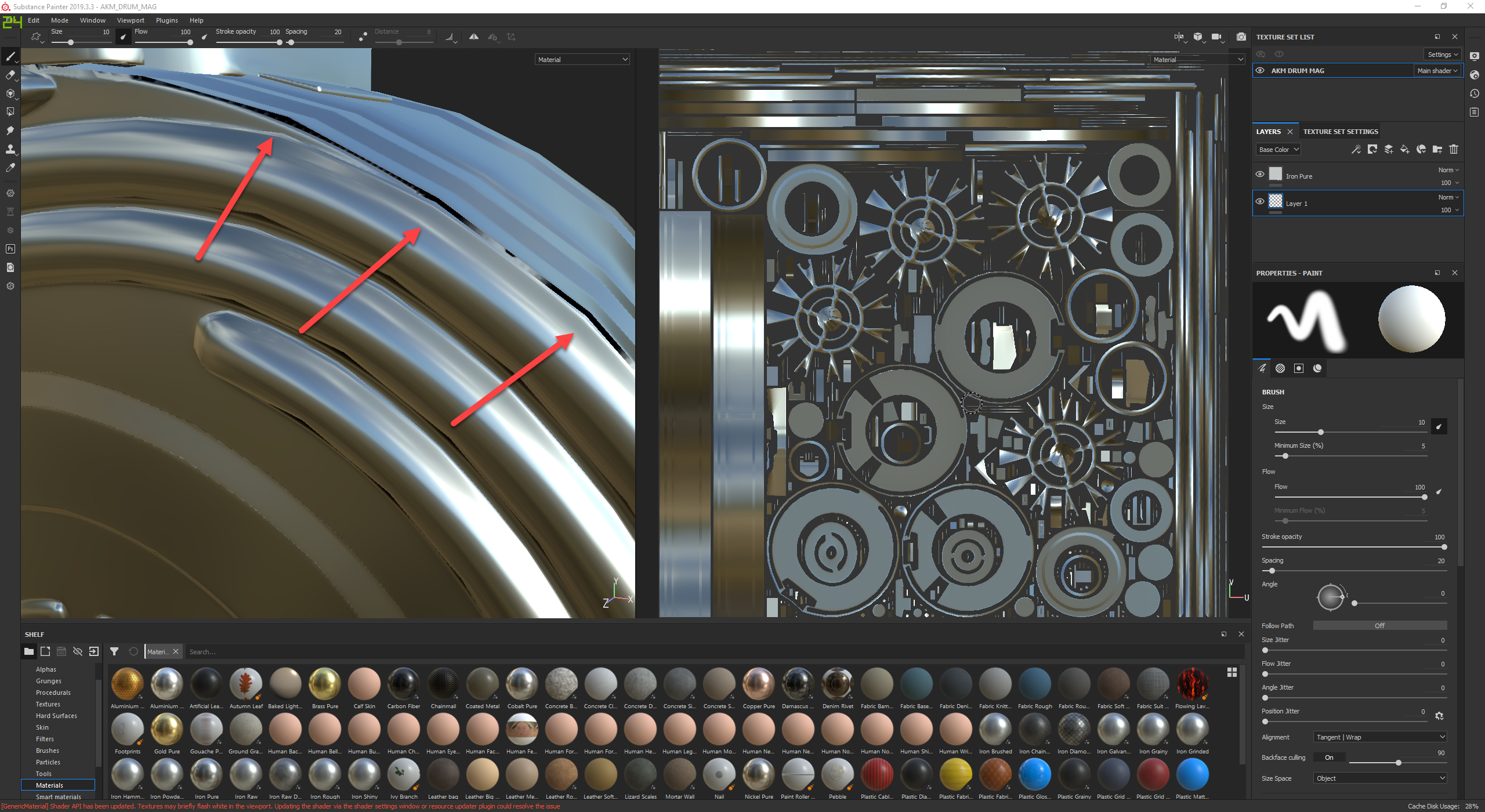
Strange baked normal artifacts. Need help figuring out how to fix it.

This is the image
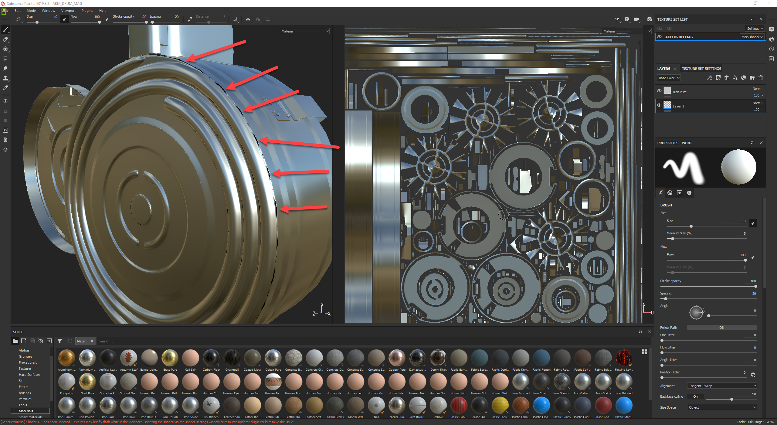
How can i fix these artifacts?

The pictures below show case why the artifacts are happening but i cant add more geometry or its not going to be usable in a game engine.
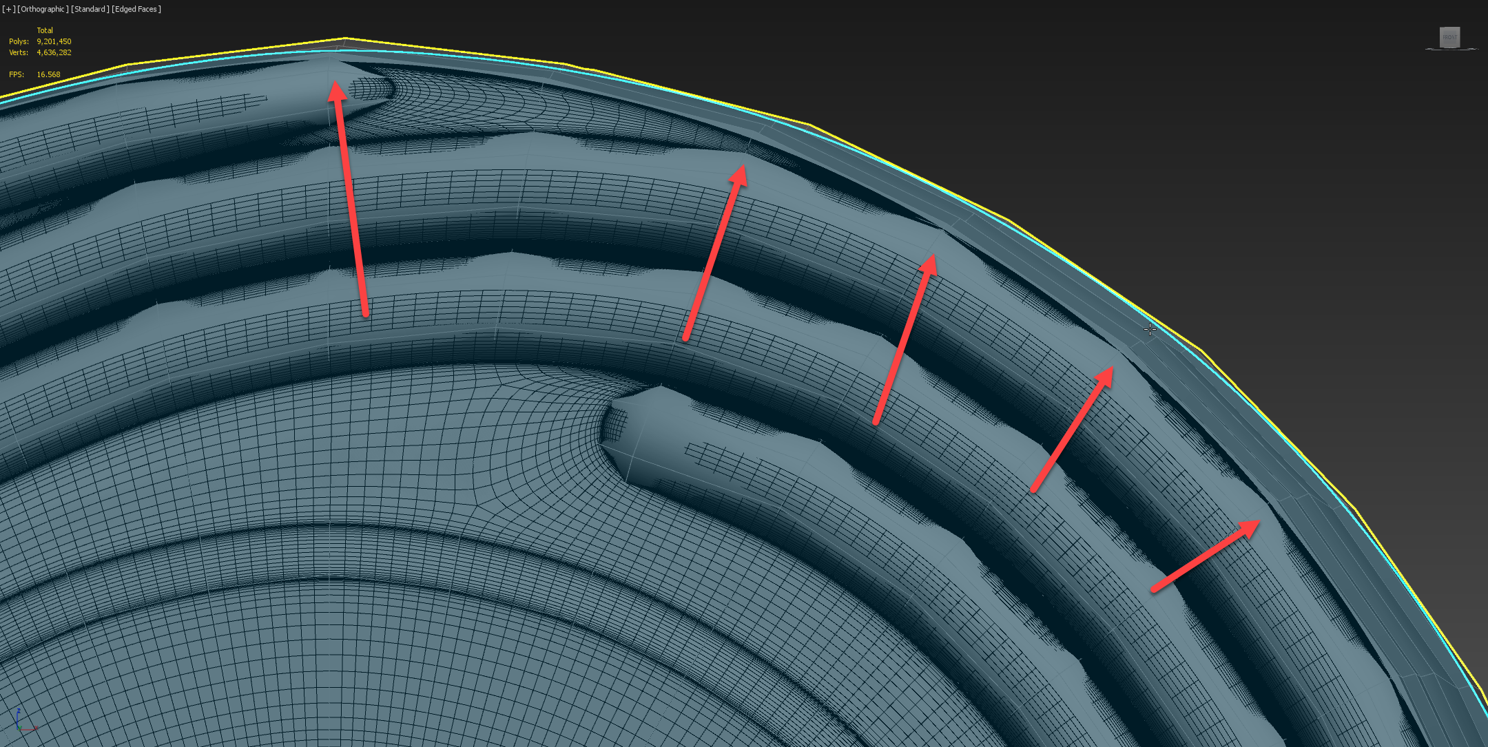
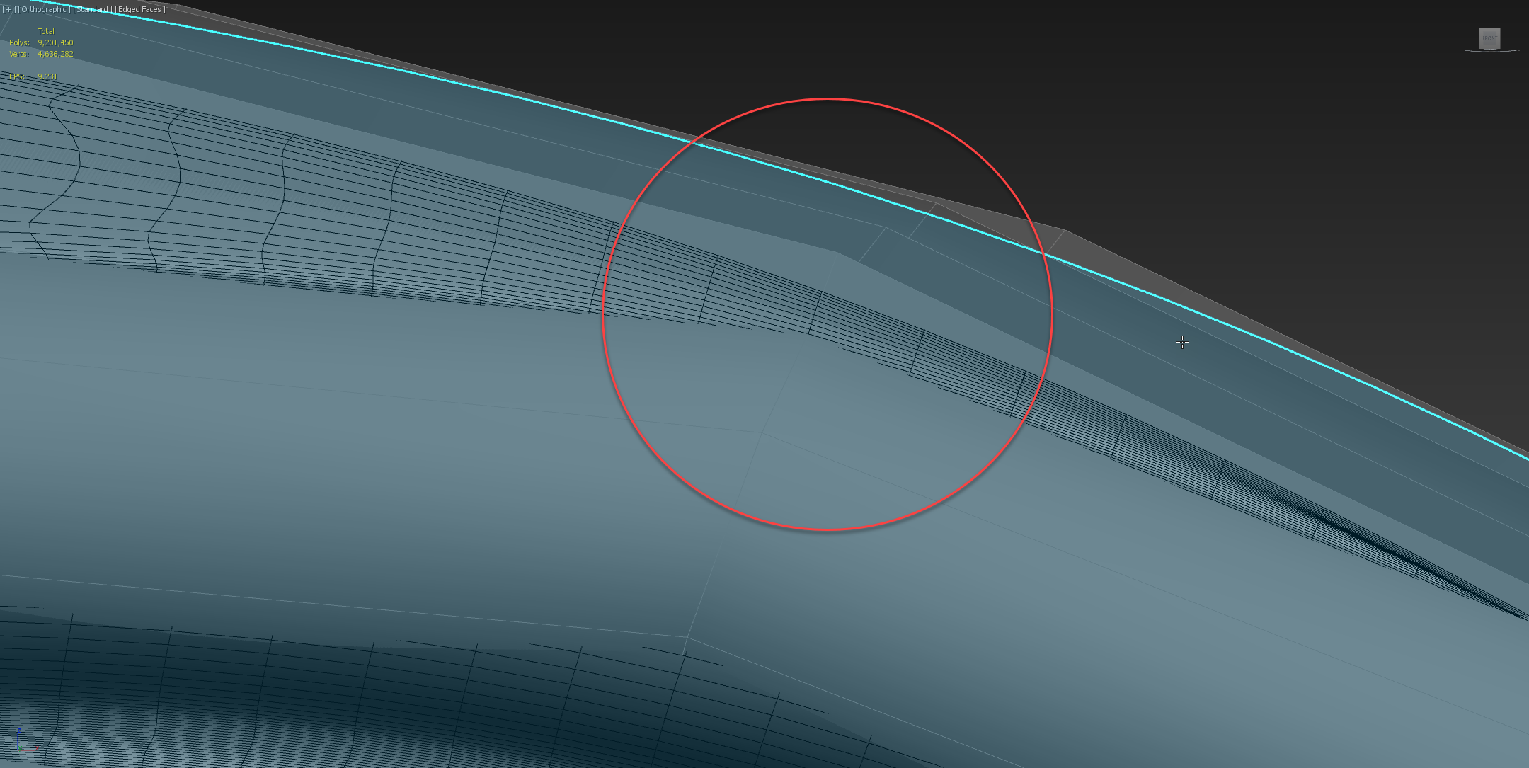
I tried adding edge loops inbetween each of the flat edges on the cylinder but the turbo smooth modifier shrinks the cylinder too much and causes these artifacts. What can i do to keep the same low poly model and still get a good bake without these black artifacts?

Also some of those spokes i know are completely screwed up in the UVs. I forgot to re copy the low poly i messed with over as highpoly and add the modifiers.

Let me know if you need anything to help figure it out.

Replies

  • Taylor Brown
    Options
    Offline / Send Message
    Taylor Brown ngon master
    I dont think you have a geometry issue on your hands, looks more to be a resolution and aliasing issue.
  • rememba_da_name
    Options
    Offline / Send Message
    What can i do to fix it?
  • Polynaught
    Options
    Offline / Send Message
    Polynaught polycounter lvl 11
    Do you have enough padding around your uv islands? Could be sampling background color instead of actual normal color.
  • gnoop
    Options
    Offline / Send Message
    gnoop polycounter
    it's always happening on  cylindrical forms.    A crazy hack that may work is having hires obj be not perfect cylinder but rather same angled one your  low res is  in this very edge . 

    An easy way I use currently is baking bevel( rounding corners)  shader on low res model  in Blender for those cylindrical  edges and then mixing it with regular normal map  in substance designer .
  • Kanni3d
    Options
    Offline / Send Message
    Kanni3d ngon master
    Either add more geo, or sink your lowpoly into your high res some more. Notice how the black artifacting matches exactly with your screenshot of your lowpoly jutting out? That black artifacting is because the rays are missing any detection from the high-res at that angle.
  • FrankPolygon
    Options
    Offline / Send Message
    FrankPolygon grand marshal polycounter
    @rememba_da_name Lots of good advice so far so try working through each issue. There's a few different types of normal baking errors showing up so I tried to replicate all of them on this shape. Isolating each issue and working through it will help determine what's going to be the best strategies(s) for the issues with your mesh.


    Figure 1: The black areas are ray misses caused by the high poly mesh falling outside of the cage mesh. Ray misses aren't always this obvious. Sometimes they appear as streaks, blotches, underlying geometry and other shading errors. The more you work with different baking applications the easier it will be to identify what's causing the issue.

    The jagged areas are caused by a lack of texture space. This can be resolved by either increasing the texture resolution or adjusting the UVs to increase the pixel density in this area. Sometimes the outer edges need to be scaled up or the internal shapes need to be relaxed to even out the textel density.

    The visible seam in this area is another type of ray miss that's related to mesh smoothing. This is commonly caused by incorrect smoothing settings from mismatched hard edges and UV splits but it can also be caused (in some applications) by using incorrect bake settings.

    Taylor's right: try going into the baking settings and increase the cage mesh offset, samples and texture resolution. Verify the results of each change and adjust the model as required. This should resolve the majority of the ray misses in your model. Here's some relevant documentation from Adobe Substance: https://academy.substance3d.com/courses/substance-painter-baking-parameters

    Figure 2: The black shadow / outline along the outside of the mesh is horizon occlusion that's suppressing light leaks from backwards facing vectors in the normal map. This can happen along edges where the low poly mesh doesn't closely follow the profile of the high poly. In this case the low poly has a hard 90° edge and the high poly has a rounded edge.

    Gnoop is right: the easiest way to eliminate this dark outline is to bevel the corners so the low poly mesh better matches the high poly. Forum member Thanez has a good explanation of why this happens and explains how to resolve the issue: https://polycount.com/discussion/comment/2714694/#Comment_2714694

    The waviness in the normal map is caused by the difference between the high poly mesh and the low poly mesh. There's a thread in the technical talk section that covers this topic: https://polycount.com/discussion/81154/understanding-averaged-normals-and-ray-projection-who-put-waviness-in-my-normal-map/p1

    Figure 3: More ray misses caused by the high poly mesh falling outside of the cage mesh. In this area there's some minor differences in how the mesh bakes based on the geometry and the UV splits.

    Eric is right: either adjust the cage mesh by changing the baking offset or editing the actual mesh to better fit the object.

    Figure 4: The bright lines that run on both sides of the chamfer are ray misses caused by hard edges that aren't backed up with UV splits. There's a few places on the original model where this is occurring so make sure the hard edges, UV splits and UV layout make sense for the object.

    There's a great thread in the technical talk section that covers this topic. In the first post there's a link to a video by Alec Moody that covers most of the key points: https://polycount.com/discussion/107196/youre-making-me-hard-making-sense-of-hard-edges-uvs-normal-maps-and-vertex-counts/p1

    Here's an example mesh that's setup in a similar way and baked without any adjustments to the cage mesh offset. The dark areas are mostly ray misses but the occlusion around the front and back edge of the silhouette is caused by the difference between the low poly mesh and high poly mesh. The crunchy pixels around the shape transitions are caused by a combinations of issues. Mostly related to sampling and texture density in those areas. This mesh is 747 verts / 1,490 tris.


    Here's the results from adjusting the cage mesh offset settings and re-baking. Nothing else was adjusted and this mesh is the same as the one above. Most of the ray misses have been resolved and the dark occlusion is still present where the low poly mesh makes hard 90° transitions. The low segment count is noticeable in silhouette but may be acceptable for third person applications.


    Doubling the segment count on the cylinder improves the silhouette and resolves most of the waviness but the dark occlusion still remains because of hard transitions. This mesh is 931 verts / 1,858 tris.


    Switching back to the lower segment count model: beveling the hard 90° angles softens the transition areas so the low poly mesh better matches the high poly mesh. This resolves the dark occlusion issues but retains the waviness issues. Depending on the view distance and camera angle this could be a passable solution. This mesh is 811 verts / 1,618 tris.


    Combining both strategies resolves the occlusion, waviness and silhouette issues. Optimize the mesh by only increasing the segment count on problem areas and reducing the segment count on central details that won't be visible from oblique angles. This mesh is 1,059 verts / 2,114 tris.


    Looking at the original model's UV layout: it appears that a lot of conical segments (Including the spiral shapes on the front of the drum) have been unwrapped as long thin strips.

    If hard edges are absolutely necessary in all of these areas and if this is the optimal packing solution then it is what it is. However: If the mesh bakes properly without all of these hard edges then it may be worth revising the UV layout since it has the potential to cause additional issues further down the line.

    Adding unnecessary hard edges and the corresponding UV splits will increase the model's resource footprint and straightening a series of concentric conical segments (that would otherwise nest) can also reduce the overall textel density. The straightening process will also introduce waviness into the texture and can make it difficult to apply human readable patterns like cammo, text, decals, etc.


    Most of the shapes on the front of the drum should be able to nest without causing any serious issues and removing some of the unnecessary splits will help optimize the mesh and UV layout. It's also worth looking for a way to mirror some part of the internal feed and winding mechanism, since it will rarely be seen and it's currently taking up a lot more UV space than seems reasonable.

    Here's an example that shows the differences between the split / straighten and nesting strategies. Another drawback to the split / straighten strategy is the possibility of normal details bleeding through or around the flattened areas in the center of the drum. The increased textel density in the nested UVs helps alleviate some of the pixelation issues near the front transition area.


    Definitely more than one strategy for setting up the hard edges, mirroring UV segments and laying out the UVs. When multiple issues like this pop up the key is to start isolating variables and testing what strategy will work best for each issue.
  • rollin
    Options
    Offline / Send Message
    rollin polycounter
    This should go right into the baking wiki!
    There are always the same questions asked about the same poorly setup meshes.

    When the basic technical understanding is missing and multiple issues are present is becomes hard without experience to see what is caused by what.
  • rememba_da_name
    Options
    Offline / Send Message
    I tried doubling the segments like you did and no matter how many times i double the outside cylinders the turbo smooth modifier is always slimmer
  • FrankPolygon
    Options
    Offline / Send Message
    FrankPolygon grand marshal polycounter
    @rememba_da_name Try adjusting the cage offsets by changing the Frontal Distance and Rear Distance values in Substance Painter's baking tool first. If this doesn't resolve most of the issues then post some screen shots of the results and the low poly mesh.

    Subdivision smoothing does tend to shrink a mesh's overall dimensions so that's expected with that approach. You may need to adjust the subdivision settings or the diameter of the cylinder so the shapes remain the correct size and fully envelop the high poly mesh. If the modifier based strategy isn't producing the desired results then the next step would be to manually adjust or redo the large cylinder portion of the drum. Images of the issues and a detailed explanation of the process will help us provide additional guidance.
Sign In or Register to comment.