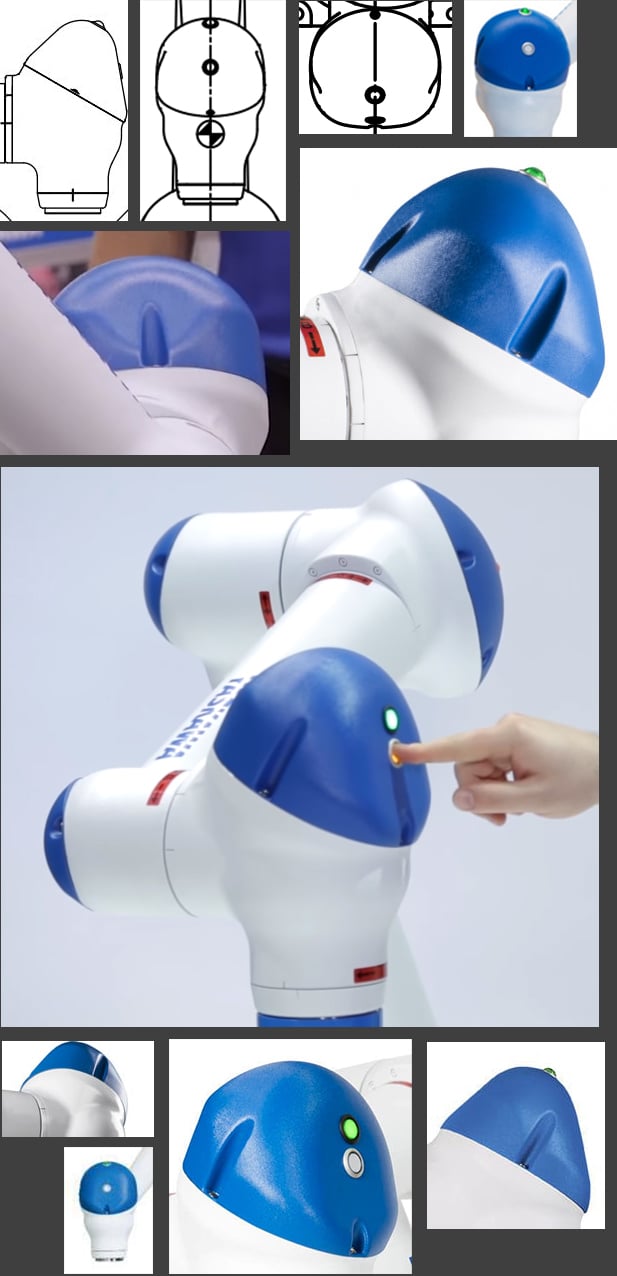
I'm almost done modeling a collaborative robotic arm, but I've hit a roadblock. I cannot for the life of me figure out how to model the blue cap on the last joint of the arm. It looks like it should be made from the intersection of a cylinder and a tapered capsule-like shape, but what exactly?
The grooves that give access to the screws are not a problem for me. It's just the overall shape of that weird cap that's giving me fits. Could one of you hard-surface experts give me some hints?
@AlexanderLawrence studying this shape which for me there's a clear indication of it's CAD (solid double precision) design ethos, basically akin too most manufactured machined products in the modern era however that said for a 'close' approximation via a parametric workflow, probably a combination of techniques i.e. Boolean operands, proportional editing, modifier stack and a bit of manual tweaking, non-destructively of course.
So for simplicity's sake I'd quad model each facet of the object separately then merge/transition them without hopefully throwing shading/distortion errors once subd is applied. No doubt a challenge for sure, any way I'll have a look at it and post a result in a couple of days or so just snow'd under with work ATM.
So I made this shape, and I was just wondering if the topology look okay, especially around the half cylinder area. I'm not 100% this is the best it can be. Should I change modify it somehow to make it look better, or is it good just the way it is?
Should I change modify it somehow to make it look better, or is it good just the way it is?
Looks okay. Could remove some dense edges, and flow the edges a bit better for subdivision, which I'm assuming this is for. Highlighted edges were added to assist in maintaining shapes too.
So I think I might be missing something here with this new piece. Another curved surface with shading issues. I thought maybe the problem might be not enough edges at first, but despite adding more the problem still seem to be there, so maybe I just need to cut it differently?
And this is the base shape, which I cute into the different pieces:
Just did a quick and dirty edit roughly 3-4 mins on the mesh. Please try to understand the concept of subd before attempting to do hard surface stuff, this thread literally filled with similar questions over and over again and people doesn't seem to read any of the fundamental basics being explained many times before.
Hi guys ! I have encountered this interesting topology issue ( at least for me ) when working on one of concept from Oscar Cafaro. How would you properly model this kind of spherical indent on sharp edge? I kinda struggle with clean topology here ...
So I think I might be missing something here with this new piece. Another curved surface with shading issues. I thought maybe the problem might be not enough edges at first, but despite adding more the problem still seem to be there, so maybe I just need to cut it differently?
And this is the base shape, which I cute into the different pieces:
My Mesh is by all means not perfect. But the steps are there to make you understand. I started with a plane and extruded it using Turbosmootmodifier. This to see that the curve is Both even in spacing and too see that the curve is correct.
I Then Applied a edit poly on top of it to work with what i have. And noticed in this case, that the curve needed more segments. This is where i added another turbosmooth and another edit poly on top of it. AS you see i cut my "panels" inbetween my existing topology.
You could also model it flat and cut in the bevels. When done, you add a turbosmooth modifier and then bend modifier. I do not recommend this mostly because your mesh probably would land on a higher account. But i will recommend it, cause sometimes it gets you a faster results.
Just to be sure I follow you, is "edit poly" the same as using the "multi cut" tool in Maya? What I fail to understand, is why do you cut inbetween the existing topology, instead of using the edges you already have? What is the advantage of that? I thought about cutting a flat plane and the apply a modifier of sort to bend it. I might give that a go too, but it might actually be more complicated. I try to not goo to high with the poly count if I can.
I think in Maya it is when you subdivide the mesh and continue working on it. In 3Ds max its just a modifier i can put above the smoothed version so it is none destructive workflow. And i cut in between those edges because the mesh itself does not contain enough segments to work with to get the wanted results. This was just to show you how i would to it. i Couldve easly gone up to as many segments as in your shot to work with existing edges. But with my mesh, i have less control points therefore easier to work with. It is always good to work with as less control points as possible.
I'm working on a ship based off of some concept art, and the shapes are very bubbly, and I'm having a hard time both creating them and putting them together. I've been trying to get the engine to look right especially, with how one side of it sorta curves inward to a sphere at the front of the engine intake. It seems like it would be super simple, but it's proving to be the hardest thing I've ever modeled.
I think in Maya it is when you subdivide the mesh and continue working on it. In 3Ds max its just a modifier i can put above the smoothed version so it is none destructive workflow. And i cut in between those edges because the mesh itself does not contain enough segments to work with to get the wanted results. This was just to show you how i would to it. i Couldve easly gone up to as many segments as in your shot to work with existing edges. But with my mesh, i have less control points therefore easier to work with. It is always good to work with as less control points as possible.
Well I tried changing the topology on the higher mesh a bit, and I think it looks a bit better now.
I also had a go at making it with less edges, and when smoothing, there is a noticeable gap between the panels.
Less edges, the worse it is. Have more geometry to support those details is what everyone was getting at
I'm almost done modeling a collaborative robotic arm, but I've hit a roadblock. I cannot for the life of me figure out how to model the blue cap on the last joint of the arm. It looks like it should be made from the intersection of a cylinder and a tapered capsule-like shape, but what exactly?
The grooves that give access to the screws are not a problem for me. It's just the overall shape of that weird cap that's giving me fits. Could one of you hard-surface experts give me some hints?
Apologies for the very late feedback on your issue, modelling this piece. Basically starting from a low poly cubesphere, then minor manual tweaks with proportional editing alongside mirror/symmetry modifier too create a close enough match:
Thanks for the links, but this takes care only partly of the challenge I'm facing.
You see all those additional bendings and differences in sizes of "rope"? That's where my struggles are (I might not clearly stated my problem before).
For example I've used helix for the handle and the bottom part, but it's extremely uniform. Maybe the good quality texture would help? Or would you model mode detailed "ropes" and then would add not that detailed texture on top of it?
Also, the main weaving part - it's very diverse in sizes and forms. Should the texture take care of this or it should be my input to model every single part to look realistic and non-repeating? I wonder how other, more experienced people would approach this stuff.
ps. I'm modeling in 3ds max and can't use any other modeling software (has to be model history stack).
Just grab some edge loops and scale them up and down. It only takes a minute to double click like 30 edge loops and scale them. Then repeat for some other random edge loops. Then just check for blatant overlap or clipping geometry. Or since you're in max you can try dropping a noise modifier on the stack and set the scale correctly.
@Lemenus I'd add a vertical edge loop to the middle of those three faces and distribute every edge loop evenly. This is more for making the silhouette of the curvature less jagged. A horizontal edge loop across all of them would probably help more to lessen the artifacts.
I mainly recommend modeling a high poly and baking a normal map later in order to override the bent face artifacts on the low poly. It would help to soften your edges too like how they are in the ref.
@perna Are you referring to me? I only tagged one person and although he was the last poster, someone else might've posted in the amount of time I took typing.
How do I model a wire like this in Blender 2.8? (Or pipes/ropes in general) I've been a 3D modeler for over 9 years and I still don't know how :c (I tried using curves but that didn't work)
How do I model a wire like this in Blender 2.8? (Or pipes/ropes in general) I've been a 3D modeler for over 9 years and I still don't know how :c (I tried using curves but that didn't work)
cant you just do a small 8 sided cylinder and make it follow the shape of the spline?
You're on the right track. Curves can be expanded into 3D geometry using the options in the Object Data tab.
For single strand safety wire: use curves to create a path then go into Object Data > Bevel > Depth and Resolution. The depth field controls the diameter of the wire and the resolution field controls the number of segments. From there you can tweak the curve how ever you want and it will auto update the 3D geometry.
For multi strand cords: create a curve based path and create a mesh based segment. From there you can use the screw, simple deform twist and array modifiers to generate the rest of the cord without having to manually model each section of it. The curve modifier at the bottom of the stack makes the mesh segments follow the path. The mesh segments (highlighted in orange) control the geometry generated by the modifiers.
Blender lets you convert mesh to curves and curves to mesh so take advantage of that where you can. Sometimes it makes sense to grab edge loops off the base mesh and use those for the basis of your curve so you're not spending a lot of time manually placing or manipulating verts.
Exactly what I was trying to figure out. Thanks so much!!
I'm getting pinching on this shape, do anybody knows what i might be doing wrong? EDIT: Ok, i figured out a solution. The corners were not exactly at the right position because I used a cylinder to create this shape. If you create the bevels on a flat surface first, add edges and use a Bend with 360 degrees you get the exact vertex position. I kept the topology as it was before.
I'm getting pinching on this shape, do anybody knows what i might be doing wrong?
Go back 3-5 pages, and I have a couple of explanations. Go back 5-10, and I have more of those, and if you keep on going back you will find between 40-50 (at least) reasons on why this error occurs. Sorry if I sound like an asshole, it's not meant to come out like that. But this is a problem that gets asked almost every page..Frequently asked questions. And some of the best artist on this page have stopped answering this question because people refuse to scroll back a couple of pages for the solution.
I'm currently modeling the low poly for this surgical light,
But this piece right here is giving me trouble. The part where the cylinder transitions into a curved swoop shape.
My modeling skills are rusty, so it's driving me up the wall. I've thought about starting with the swoop shape first, and bridging it with the cylinder, but I can't wrap my head around where to go from there.
@wirrexx Yes I know it's a question that get asked often and i did scroll back and read a lot of solutions. I was getting confused because i thought i was following the same topology that was getting recommended and still getting issues. Sorry if that sounded ignorant
@wirrexx Yes I know it's a question that get asked often and i did scroll back and read a lot of solutions. I was getting confused because i thought i was following the same topology that was getting recommended and still getting issues. Sorry if that sounded ignorant
if you're working with a modifier stack you can even get away with shitty geometry, since the bend modifier will bend your bad topology into the right shape
I’m a bit stuck one something that probably all of you find laughably easy. I’m in the process of modeling a shoe that has some rather tight curvature on some edges.
I’m trying to get by with as few base polygons as possible to keep a smooth surface. If I just straight up model the section without looking at the underlying geometry, the subdivisions will soften the curves way too much (fig.1)
So I did pinch the top vertices together to have a tighter corner and that works but it looks kinda wonky to me? (fig. 2). What do you guys think, maybe I just need more geometry? But I’m trying to keep the surface as smooth as possible. So kind of unsure here.
The first one is my result and the second one is from Spyro, i got a pretty similar look in 3Ds max, but took me a really long time so wanted to hear you opinion on a good way to model that?
Model the stones separate. You can bake them down to a lowpoly version later. You don´t need to model everything as one piece.
Thanks can you expand on that? the overhang is already a model by it self I have just set it on the tower. or are you talking about creating the small stones under as separate pieces and place them on?
Yes, i would model the elements of the overhang and the roof out of seperate stones. Its much easier to adjust.
thanks will try that do you got an example where you can see it done some where just for reference?
Replies
Model the pieces flat. project them onto the helmet using ShapeMerge/FFD (in max atleast, probably equivalent in other packages)
@ 5:40
The grooves that give access to the screws are not a problem for me. It's just the overall shape of that weird cap that's giving me fits. Could one of you hard-surface experts give me some hints?
So for simplicity's sake I'd quad model each facet of the object separately then merge/transition them without hopefully throwing shading/distortion errors once subd is applied. No doubt a challenge for sure, any way I'll have a look at it and post a result in a couple of days or so just snow'd under with work ATM.
So I made this shape, and I was just wondering if the topology look okay, especially around the half cylinder area. I'm not 100% this is the best it can be. Should I change modify it somehow to make it look better, or is it good just the way it is?
Looks okay. Could remove some dense edges, and flow the edges a bit better for subdivision, which I'm assuming this is for. Highlighted edges were added to assist in maintaining shapes too.
And this is the base shape, which I cute into the different pieces:
I Then Applied a edit poly on top of it to work with what i have. And noticed in this case, that the curve needed more segments. This is where i added another turbosmooth and another edit poly on top of it. AS you see i cut my "panels" inbetween my existing topology.
You could also model it flat and cut in the bevels. When done, you add a turbosmooth modifier and then bend modifier. I do not recommend this mostly because your mesh probably would land on a higher account. But i will recommend it, cause sometimes it gets you a faster results.
What I fail to understand, is why do you cut inbetween the existing topology, instead of using the edges you already have? What is the advantage of that?
I thought about cutting a flat plane and the apply a modifier of sort to bend it. I might give that a go too, but it might actually be more complicated. I try to not goo to high with the poly count if I can.
I also had a go at making it with less edges, and when smoothing, there is a noticeable gap between the panels.
AlexanderLawrence said:
I'm almost done modeling a collaborative robotic arm, but I've hit a roadblock. I cannot for the life of me figure out how to model the blue cap on the last joint of the arm. It looks like it should be made from the intersection of a cylinder and a tapered capsule-like shape, but what exactly?
The grooves that give access to the screws are not a problem for me. It's just the overall shape of that weird cap that's giving me fits. Could one of you hard-surface experts give me some hints?
Apologies for the very late feedback on your issue, modelling this piece. Basically starting from a low poly cubesphere, then minor manual tweaks with proportional editing alongside mirror/symmetry modifier too create a close enough match:
https://www.youtube.com/watch?v=7t-oCeApEI8
without distorions (stretches)?
EDIT:
Ok, i figured out a solution. The corners were not exactly at the right position because I used a cylinder to create this shape. If you create the bevels on a flat surface first, add edges and use a Bend with 360 degrees you get the exact vertex position. I kept the topology as it was before.
But this piece right here is giving me trouble. The part where the cylinder transitions into a curved swoop shape.
My modeling skills are rusty, so it's driving me up the wall. I've thought about starting with the swoop shape first, and bridging it with the cylinder, but I can't wrap my head around where to go from there.
thanks!
I’m a bit stuck one something that probably all of you find laughably easy. I’m in the process of modeling a shoe that has some rather tight curvature on some edges.
I’m trying to get by with as few base polygons as possible to keep a smooth surface. If I just straight up model the section without looking at the underlying geometry, the subdivisions will soften the curves way too much (fig.1)
So I did pinch the top vertices together to have a tighter corner and that works but it looks kinda wonky to me? (fig. 2). What do you guys think, maybe I just need more geometry? But I’m trying to keep the surface as smooth as possible. So kind of unsure here.
Any suggestions? Thanks and cheers.
Another technique to utilise, is to sculpt the details then apply an ffd/lattice modifier too deform the mesh into a stylised aesthetic.
https://www.youtube.com/watch?v=sZcfLh8eaC4&list=PLA7A2AE046E0B5552&index=1