High poly CAD model to Low poly - Normal Map experiment
So I have a CAD model that is far to detailed and I would like to capture some of this detail in Normal maps.

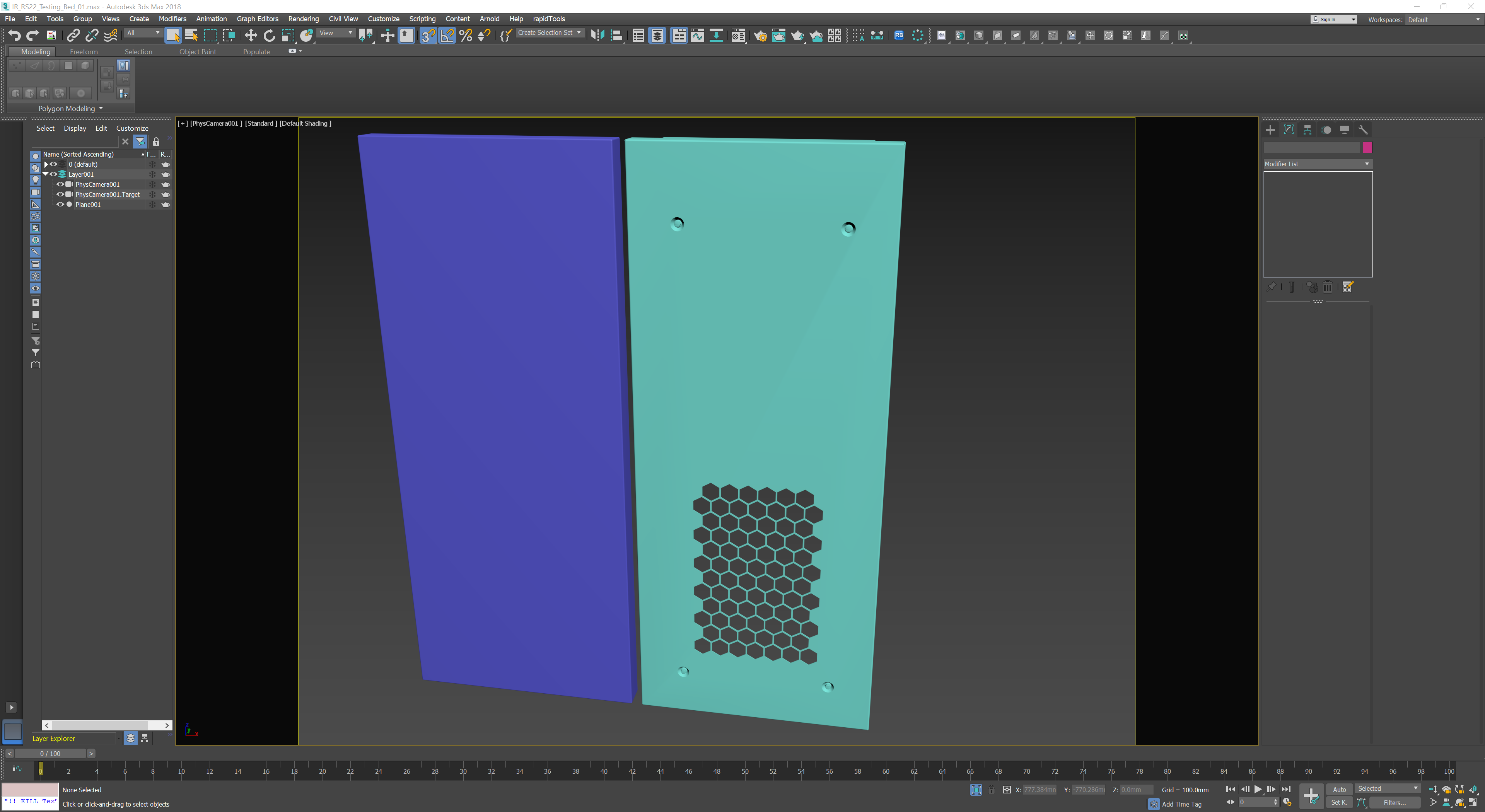
To test out my plan I chose this panel that is a cover for a section of the model, I've created a simple plane with chamfered edges to project the detail on to.
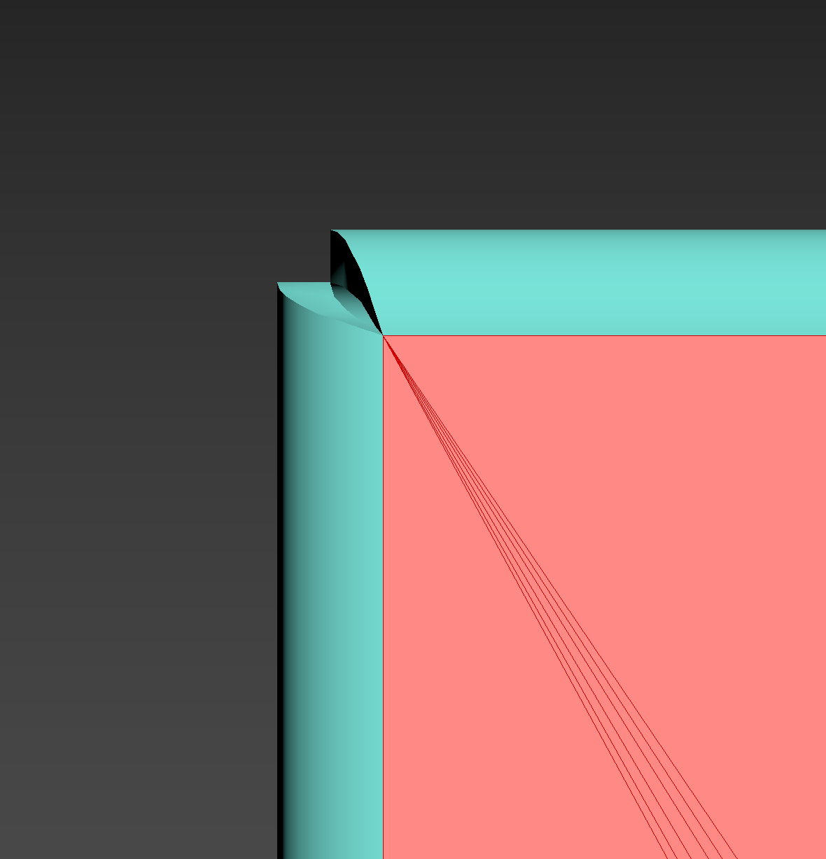
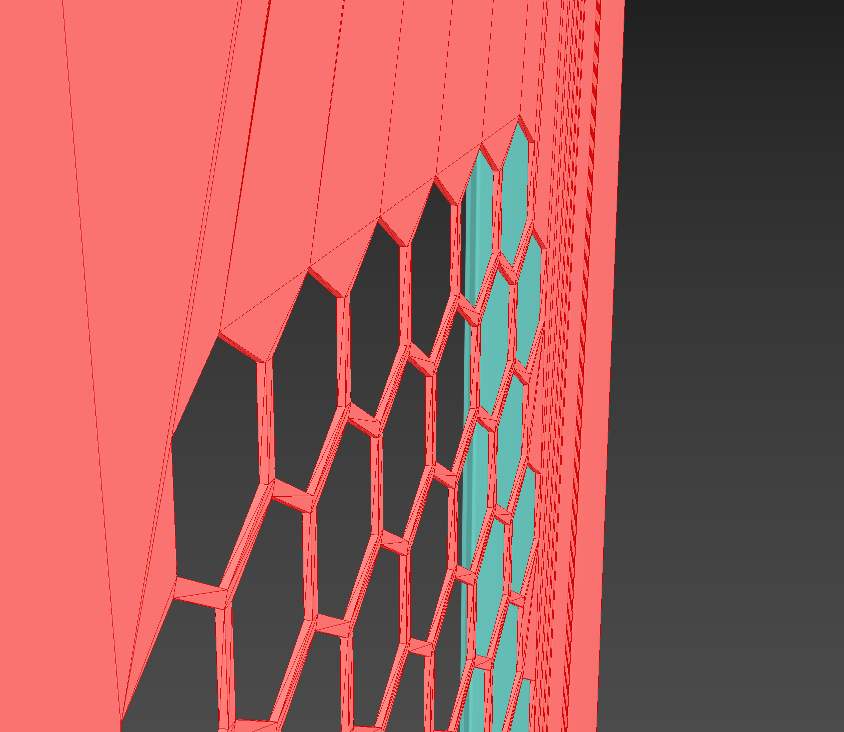
The model has some nasties, for example the corners of the panel (Below)

Because I'm only concerned with detail from the front of the panel how would people approach this task?
Is there a way of creating the thickness of the metal within the material?

Thank you in advance for any help and advice.

To test out my plan I chose this panel that is a cover for a section of the model, I've created a simple plane with chamfered edges to project the detail on to.
The model has some nasties, for example the corners of the panel (Below)

Because I'm only concerned with detail from the front of the panel how would people approach this task?
Is there a way of creating the thickness of the metal within the material?

Thank you in advance for any help and advice.
Replies
The section I think the Normal map would work best is these indents where the screws are located.
Thank you @Dihemi this is very useful and I will certainly try your suggestions when presented with the next CAD model. Unfortunately this particular model was supplied in 3Ds format, I will pass on your information to the company that normally deals with the export/import process.