In need of help understanding general normal mapping concepts
I've been trying to learn basic modeling since about Feb of this year in order to build and texture some farm implements in Blender to use in Farming Simulator 2015. The impetus is that most modders rarely texture their work and the results are an eyesore in-game. Actual modeling of high poly things is going well and is the easiest part. I'd like to eventually understand how to mirror low poly objects along with their normals and AO, but I'm not able to reproduce the basic examples I'm finding in tutorials here or apply them to my own models.
My progress starts and ends with adding edge loops to a cube primitive, using a displace modifier to create a cage with full smoothing to achieve averaged normals, and baking out a "high poly" cube with beveled edges. I get the expected result. A low poly that cube looks great, beveled edges, no seams.
I've read the "making sense of hard edges, uvs...etc" and a couple of EarthQuake's posts where he demonstrates the value of edge loops on cylindrical objects many times.
When I go to bake a cylindrical object using a smoothed cage and edge loops as described in those threads, this is my result:

That's not at all what I expected. I thought we went to all that work creating edge loops and increasing our vertex count moderately in order to specifically eliminate this exact issue according to those threads I mentioned.
Further, once I remove all the extra loops and just use a basic hectagonal cylinder and bake without a cage, the result is perfect.

Here I don't understand why I went to the effort of putting in edge loops and what happened for them to result in the problem that they're supposed to solve. Actually, I don't understand how this result is possible without skewing. The explanations made sense in that the loops allowed the effects of normals at the edges to be separated from those along the length. I don't know how much of this is a blender thing and where my misunderstanding is.
I tried other times to use the averaged normal setup using edge loops and I can't get any reasonable result that way. Here I tried using edge loops and a cage again. The hex nut area is shaded flat and the threads sticking out are a smooth group on the low poly and I've got UV seams at those hard edges. The nut bakes with no seams but the cylindrical thread portion is a distorted mess with artifacts.
In one of the posts, there is a section on Destructive Baking workflows and I think I used that specifically to come up with a method that works. I'm not just a little frustrated by the fact that what I found to work seems to be explicitly what the author, an expert, recommends against.
If I take that nut and threads and bake it in three steps I get a great result. Bake the nut with a cage, move the forward bolt face UV island out of the UV space, bake the threads without a cage, then finally bake the bolt face.
That seems like too many steps, even if only by one. So my conclusion is that in the future, this should be modeled as two intersecting meshes just to simplify the baking. I don't know if that's right.
The very last thing I tried failing at was understanding how to avoid seams in the basic beveled cube model by putting UV seams on all the edges and adding significant "padding" between the UV islands. This is explained in numerous posts across the internet as a quick solution to seams on the basic beveled cube problem. No matter the amount of "padding" I put using separate UV islands, I still get seams on my model.

I gave up last month because it felt like nothing I read or do seems to work as described so I can't figure out a workflow to finish making the few parts I want because I've still got to learn how to combine all these objects in one UV and develop a workflow for making changes without having to re-bake everything if there's one piece or even just a face that I'd like to adjust. My project may not be big enough for this to seem like a huge concern and of course no one but me is going to see it, but it's the principle of the matter of learning a new subject correctly and having a workflow that's fundamentally sound in order to continue.
Replies
1: To me it looks like you are still adding a little skew. If you look directly down on the mesh from the top do the cage edge loops and the mesh edgeloops line up? if not then the raycast is not perpendicular.
2: I'm guessing you are not averaging the direction of the raycast, so the raycast is following the mesh normals. And there is a hardedge at the cylinder cap. Hence the raycast direction is perpendicular and not skewed. At the expense of a projection gap at the edge of the cylinder cap, if it's capped at all that is. If it's not then it'll work that way. If it has an end cap and a hard edge, Then you'll get a good bake everywhere, except where there is a gap at the hard edge.
3: Dunno whats up with your bolt. But the only thing you should be having issues with is what to do about skew on the threads. but you are having smoothing and edge errors it looks like.
4: Use averaged normals in the projection raycast/cage. The black lines are gaps in the projection, so the cage/projection has to be averaged, don't use the mesh normals as there are hard edges, eg you want 1 normal direction at the corners of the box not 3 different ones based off the hard edges of the box vert normals.
Thank you for your thoughts! I'm encouraged and it's got me thinking.
1: That's super interesting because the answer is absolutely not. I'm probably adding a lot of skew now that you mention it. I have been led to believe I will never have a situation where the edges align. I'm hoping you can understand why when I say that every intro to baking with a cage I've read or watched on youtube explicitly shows a step where you copy your low poly model and then either scale it or apply a displacement modifier. The edges will never line up on any orthogonal view using those methods. Is that an actual requirement because that would mean the raycasting is being done in an intuitively obvious way instead of whatever I've been led to believe/trying to figure out? That would change significantly change how I size the low poly as well.
2: Oh. Thank you for clearly describing what's going on. It's the "hard edge" or break at the cylinder cap that allows the normals along the length of the cylinder to not be skewed. There is the telltale gap at the hard edge. I did a version of the long screw threads with edge loops, no hard edge, and no cage and didn't really understand how I still got a good looking result with no gap. There's a tiny bit of skewing at the edge. Is that a function of the width of the edge loop there? I had to really look to see this so I'd probably just go with it as-is and use this method on future objects without more practical advice.
3: I tried creating a cage with averaged normals at the same size, a simple duplicate, of the low poly so the edges will align for raycasting and blender simply refuses to bake using that cage. If I scale or displace the cage, it does bake, but it does what I showed, distorting the entire thread section. I'd say this is still an unresolved problem I'm going to be facing with any object where I've got more than one smoothing group.
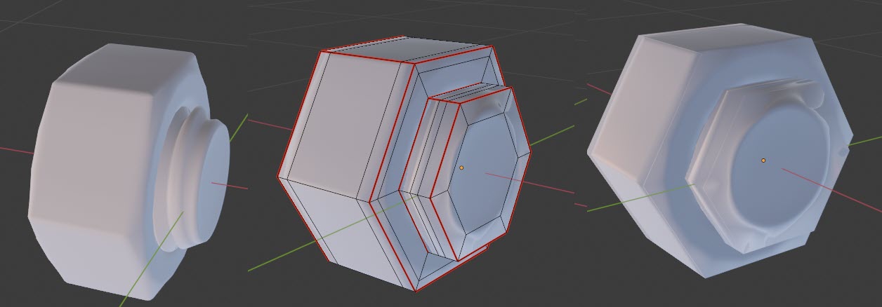
4: Is that what they mean by "separate smoothing groups" when referring to a lineup of cube models like shown here? I'm looking at the 2nd one from the left. It's not just that they separated the UVs, it's also baked with an averaged smoothing group cage? That's the only way I've been able to make it work and it does actually look better than a cage alone.
I'm seeing some interesting ideas. I'm still a bit lost on practical applications. I've got a part here that I'm not able to figure out how to bake in one go. If I size the cage large enough to encapsulate the vertical bevels shown by the blue vertex groups, the area in red becomes distorted and vice versa so I have to bake it in two stages with two separate cages. That doesn't seem right since this really doesn't seem like that complex of an object.
• You are very much on the right track with how thorough you are with your investigations. Just one thing though : when it comes to things like cage setup, so-called "best" practices, and so on ... do not trust anyone blindly unless you 100% understand the why.
• Taking a bit of a step back consider this : at the moment you are focusing on some very subtle yet important things ... that some less precise artists never took the time to understand even after years in the industry. I do think your approach is the good one (and I can guarantee that you'll have all your issue solved here in this thread in about a week or so) ; but also keep in mind that there are other options ...
... like for instance modeling these assets as simple (but dense enough) ingame models, using hard edges where needed ; giving them some nice, straightforward UVs ; and unly osing the normalmap for tiny surface details, but not for high to low baking. Or perhaps baking down some tiny highpoly elements just as you need them, where you need them. This could get you to a great looking result in a fraction of the time - something along the lines of GTA3 car models.
Also, here's what's happening to your cube :
For a cube with all hard edges to bake right you need to have all 6 faces split off from each other in the UVs (to avoid pixel contamination over the instantly changing shading of the hard edge), and bake using a cage that doesn't break at the hard edges (or bake using a software that does not automatically split off rays over hard edges when not using a cage. So me do, some don't).
• As for your cylinders : you need a custom cage that is thicker than the low, but with the cylinders "end caps" of both the low and the cage coplanar. Meaning that the rays will be case at a perfect 90 degres everywhere from the surface of the cylinder.
• But to go back to the earlier point of using other approachers : unless some very specific texturing/weathering is required, you likely don't really want to bake such threaded rods as individual parts in the first place anyways. You are better off preparing a nicely tiling thread normalmap that you can then map onto any cylinder that needs it. You could have many little useful things like that packed into a corner of your UVs, for every model that needs it.
1: Yes. When thinking about projection and skew in baking, ideally you want to think about how you size the lowpoly as well as how and in what direction you scale a cage. which is often as little a possible, ie make the low fit the high poly or suffer. On a cylinder you could just scale the cage in the axis around it and never along, and the projection should work. It's a limited solution that really only works in this sort of instance.
2: yeah the extra edge loop is just padding where the skew starts and ends, constraining it to the very ends. But the idea applies as a general concept. If you have detail just about anywhere on a mesh, an edge loop/vert right on/over it is not too uncommon. It's not always obvious why there is a loop/vert in a low poly example, sometimes it's because the artist was planning ahead a little.
3: Well your bolt isn't really going to look good baked like that, even if the cage was working perfectly for most of it> a 6 sided cylinder low for the threaded very rounded part is going to be crap, the low and high are just too different. getting edge normal information from either just beveling a 6 sided cylinder or bevel shader and compositing the threads into the normals will probably just be a better idea. It's just the limitations of such mismatched geometry.
4: Separate smoothing groups is just refering to the low poly having hard edges, nothing to do with the cage, but yes the cage used here is 1 smoothing group.
I would look for is some cage options. Checking blender docs I found this> "Cage ExtrusionDistance to use for the inward ray cast when using Selected to Active and Cage. The inward rays are casted from a version of the active object with disabled Edge Split Modifiers. Hard splits (e.g. when the Edge Split Modifier is applied) should be avoided because they will lead to non-smooth normals around the edges."
this seems something you need to understand how it works in blender. It's saying something about verson of active obejct with disabled edge split modifiers. That's what you want to fix the cube problem.
You have different options for that weird bracket thing too. Maybe try to make the low poly geomerty already encompass the high poly, the blue vertex groups could already be encompassed by the low poly nearly completely, that way you don't expand the cage so it goes all over the place. You should be able to bake that okish,
But since there isn't much to the high poly except basically proceedural modelled bevel information You probably could just find a way to get beveled edge information into the normal, like for example using a bevel shader and not bother wiith baking high to low. Another way might be to split the mesh into 2 pieces if it's a real pita.
I am still using an ancient approach of re-rendering object/world space normal map texture into tangent one. No separate Hi res objects, just a few bevel modifiers. Sometimes just bevel/rounding corner shader. No tedious cage tweaks .
That way you miss sometimes a proper curvature bake from a baking soft but there are lots of workarounds starting from offline shaders that could mimic all of this. Pointiness in Blender for example.
Sometimes I don't even need to texture paint . Offline shaders/materials in many offline renders working in world space instead of UV space + edge detecting do it all for me . Much easier and much more universal too in my opinion and I did it long before Substance Painter surfaced. You just drop and forget such a material then bake the surface vs non stop tweaking in Painter fighting with UV space projections or even triplanar one and endless quirks .
The only condition is your subdivided or sculpted model you take your object space normal map and material from should have same UV.
IMO it's just simpler than all that ray tracing from low to hi with always distance and ray miss issues
ps. And more over this approach allows you to not care of steady texel size at all .
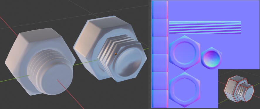
I've been really enjoying going through the comments here. I understand baking out these bolts and threaded things isn't practical for asset modeling. I thought it was good case-study for sets of low poly coil springs I've been trying to figure out how to make.
The problem with really getting into what's being said here and unfortunately everywhere else on this site (Understanding averaged normals and ray projection/Who put waviness in my normal map? — polycount) is that I'm hard stuck on the technical application. I cannot successfully bake out a cylindrical object using a cage in Blender 2.83. I'm using 2.83 because it's the latest version that is still back-compatible with my game.
In a first ever, I was able to get the details on the smoothed length of a cylinder to bake without skewing by using a cage, however no normal information is baking at the cylinder ends with the end of the cage and low poly model being co-located.
It looks like the raycast is a product of the difference between the cage and the low poly, I don't know the math but it obviously all went to zero in this case. What's going on here? I don't see anyone talking about such limitations with any other software, nor even blender since the focus is always on using the cage to relieve the seams created by hard edges. In looking closely I see that Earthquake put his low poly caps inside of his high poly models, I dunno if that was just for demonstration when comparing the topology. What it comes down to is that I don't have a basic methodology from anywhere to follow.
What are some steps that would or should be universally reproducible in order to take my aptitude out of the equation and make sure what I'm trying to do is even technically possible?
I was trying to mimic what I thought was a very simple cylinder with bevel and groove I found at the bottom of this thread: Baking a tube — polycount.
Well, this test cylinder of yours looks pretty much perfect so I don't think you have much left to figure out really.
The one thing to keep in mind about baking in Blender is that after a recent-ish update to the baker (around 2.8 I believe), rays are only cast inward. And if nothing is reached (because of the lowpoly partially being inside the high for instance), the rays will keep on searching for something to hit ... until they hit the other side of the high. This can be confusing because when looking at the resulting normalmap it can look like the search distance needs to be increased (because of the odd patches of colors showing here and there looking a bit like missed castings even though they are actually hits on the opposite side of the high), whereas it is actually the automatic pseudo-cage inflation that needs to be increased, for the rays to all start from outside the high.
As for ray direction it's really quite simple : if you provide a manual cage, then you can control each ray individually by moving the verts of the cage as needed. If you use an automatic "pseudo-cage", then you only have control over search distance and cage inflation. And if you provide no cage, then the rays follow the surface normals. Meaning that you likely want to turn on vertex normals preview in order to get a feel of what will happen during the bake.
And ... that's it really !
pior What you calling pseudo-cage . Is it something new in Blender ? Inflation is "extrusion" , right?
I don't really use baking in Blender due to lack of AA so know that part not very good
Oh, that's just my way of describing the fact that one can input push/inflate/extrusion and ray distance values as opposed to using an actual geo cage.