topology for subdivide
polycounter lvl 5
hi
I hope you will understand me
I'm trying to create a mouse model.
I made a model base, low poly

then I split the model into a segment, add thicknes, to create grooves between the segments

then i add support loop to get nice smooth grooves, and got some issue


and there was a problem, grooves is noot smooth as i expected.
only what I came up with, is the mesh affter add support loops it is not perfect aligin with top object after subdivide.
so i add som extra loop to make this mesh perfect aligin, but i do not know if is it good wey to do.

please help how to deal with this issue
Replies
The curves in the base mesh subdivide cleanly because both sides of the grooves have the same number of segments. Adding the support loops to the two adjacent splits in the shape below the groove changes the segment spacing on the lower half of the curve. Which does sharpen the corners but also causes them to overlap with the upper half of the curved groove.
There's a few different ways to resolve this kind of smoothing artifact. Deciding which approach makes the most sense will depend on how soft the edges need to be and whether or not the model needs to be split into separate meshes.
If the subdivision model will only be used for rendering then it probably makes sense to keep the relatively tight support loops and mesh splits along the object's parting lines. Since the model's existing topology looks workable: the easiest solution would be to shrink down the outer vertices of the sharpened corners, preferably before adding the support loops.
Moving the corner geometry down compensates for the upward distortion caused by the abrupt change in the segment spacing. This will leave a small gap between the individual meshes but everything will fall in line with the larger curve when the subdivision is applied. How far the corner vertices need to be moved will depend on the shape of the arc, number of segments in the curve and the width of the support loops that are causing the distortion.
Enabling subdivision preview will make it easier to line everything up. It may also be a good idea to constrain any move operations to the edge normals of the surface. This will help prevent the adjustments from disrupting the compound curvature of the underlying surface.
If the subdivision model will only be used as a high poly for baking then it probably makes sense to use looser support loops and it may even be worth merging some of the mesh components to simplify the shapes. A simple block out can be used to establish the topology flow of the larger forms and this can be refined in stages to resolve any potential issues around the smaller shapes. Creases and edge weighted bevel modifiers can be used to preview loop smoothing behavior while working through the topology.
Once the basic loop flow is established, the loop path can be created with a single bevel / chamfer operation or multiple inset operations. The depth of the parting lines can be added by shrinking the middle loop on the path inwards. Final support loops can be generated using an edge weighted bevel modifier. Below is an example of what that process could look like.
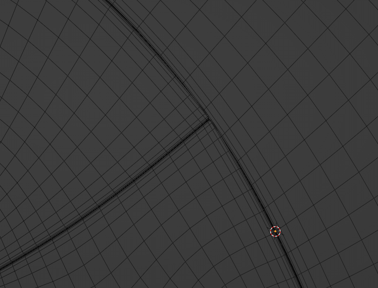
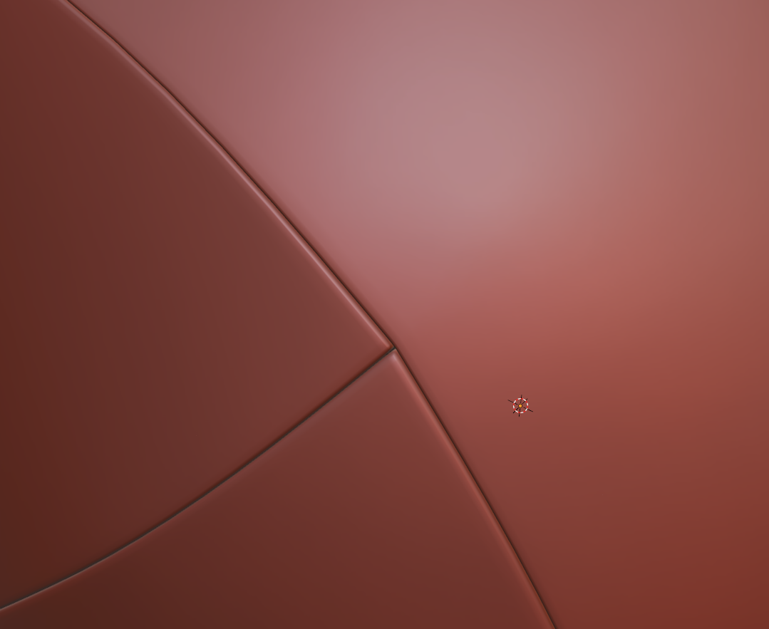
Having a continuous base mesh provides some additional options for the topology routing. It's possible to use a 5 sided E pole to direct the flow around the split in the shapes or use a triangular quad to reduce the perpendicular support loops without adding segments to the primary curvature. Here's a close up look at the topology near where the corners meet the top curvature of the parting line.
Support loops can be organized with several different routing strategies but the goal should be to constrain any minor smoothing artifacts to the narrow area between the support loops where it won't be visible. Generating the support loops with an edge weighted bevel modifier means it's possible to adjust the number of segments and width of the support loops as required. Without having to manually re-work each individual loop.
While a continuous mesh can be used to simplify the high poly geometry for baking, it may not be the right choice for every shape. Large, complex objects should generally be broken up into individual components that match the desired fidelity of the in-game model. Splitting a mesh along an object's seam lines also allows each part to have a slightly different polygon density. Which can make it a lot easier to establish seperate topology flows on individual surfaces. Just be sure that the adjacent shapes deform as expected when subdivision is applied and adjust the shape of the base mesh as required.
Recap: Complex objects should generally be broken down into individual parts that are modeled separately. It may be necessary to adjust the shape of separate mesh elements that are adjacent but have mismatched segment counts or additional support loops. Certain shapes can be simplified by merging adjacent shapes. Establishing the topology flow in several different stages can make it easier to create continuous meshes but it can be challenging to plan for every surface detail. Take the time to think about how the subdivision model will be used and optimize workflow decisions around the desired results.
wow thank you so much for that explanation
Very nice topology, I will pass this onto my work mate who loves a bit of even flow.
hi
i'm trying to add detail for wire, but it generates a triangle in the mesh. Evry tutorial always says to model with quad, but right now it looks like triangle is the only way.
is there a way to model it with quad or can i use triangle when it is needed.
quadonly is a weird myth that is mostly only valuable in VFX. i think in your case, likely creating a bakeable highpoly, anything goes as long as it shades well. if its a flat surface, ngons or tris are perfectly fine. in some cases (5sided) ngons also shade better on curves than trying to clean it into a quad.
of cours eif your intention is to sculpt it, in zbrush you'd have to clean out ngons as it can not handle them.
the rule of thumb would be, if it doesnt deform and shades well, anything goes.
but if you really, really want to make this triangle a quad, all you need is one edge. its an ugly quad, but a quad nontheless
if you want a nicer solution
I have to admin 3d modeling is harder then it looks like. Now I trying to add support loops to have nice sharp corner and I have more issue. Why quad only mesh is only in \VFX?
this specific issue has been tackled hundreds of times in this thread, you'll have to do some digging but it is there
https://polycount.com/discussion/56014/how-the-f-do-i-model-this-reply-for-help-with-specific-shapes-post-attempt-before-asking/p1
Maybe I am blind or maybe stupid but can't find the solution for my case. I found some similar but they did not help me to solve a problem. the are mostly on flat surface but mine are curved.I
also read advice in that thread, and I found that higer topology can be a good idea, so I apllyed subdivide before extrude that part and it gave me better quality but still cant get realy nice sharp corner.
I tryed evrything and dont know what I can do more, only wey to have this nice sharp corner is to have suport loop along the entire model but it generate hard enge on entire model.
The thread is really long, this happens a lot but it would take some sifting to find the examples.
Try reading through this and see if it helps you.
What you're seeing makes total sense after understanding how things are subdivided. Keep searching through the other thread if you have time, I know for sure there are some examples that almost perfectly match your shape.
Also see:
https://www.artstation.com/blogs/frankpolygon/o7Pg/sub-d-modeling-cylinder-and-rectangle-intersections-fillets
https://www.artstation.com/blogs/frankpolygon/e72b/sub-d-modeling-cylinder-to-cylinder-intersections
I figured something out, the point is to try to use original edges as a support loop, but for this i need appropriate mesh density.
So that means my model suck and i need to remodel it a little.
example, i used 32 edges cylinder, with 64 or 128 edges it would be even better, but workin all time on 128 edge cylinder would be a little hard
am I right ?
that works, there's no pinching or artifacting, which is all that matters.
"use original edges as a support loop"
bingo
i believe so, yes. as stated, if the shading looks good, then its g2g.
from what i recall when the "How The F*#% Do I Model This?" thread was first created, often the reply to a question was "add more geometry". but, you'd also be correct that the more verts you have, the more difficult it will be to manipulate and control surfaces.
FrankPolygon's earlier example, of creating a mouse model with contiguous geometry, is an example of planning for the next modeling step or phase, building up the complexity of a model for more control. he first defines the larger form, then positions the seams by its loop placement, then cuts in edge support loops into the loop flow, which allows him to clean up the area manageably with small slides and nudging of verts.
Higher topology is indeed the only way to get really nice results. When I want nice tight corners, I actually put one support loop like you have, close to the corner, and then put a second one between that and the original loop. Using 2 support loops at edges will give you beautiful tight corners with no artifacting (depending on the geometry of course, but with shapes like you showed, it'd be perfect)
Hi, I'm writing a bit late, but I did rewrite some tutorials and i get pretty nice effect
And this is how i got this, I realized that subD Modifier need some geometry to work good.
For example we cen get nice cylidrical shape add subD to 4 side cylinder, but its work better if we have 8 for example
The issue what i post before resulted from low density of my mesh.
So I add 1 lvl of subD to my model and clean mesh a little, then I divide my mesh to separate part, add thickness, and then add support loop with bevel modifier what is non destructive method
And it gives me very good effect.
My conclusion is that SubD modifier needs mesch which is built with this modifier in mind, if its too low there are some issue like i had before, but also can't be to high because it's harder to manipulate.
My low poly mesh works very nice without subD, just to add smooth shade play some with vertex normals to get smooth shading on corner and there is.
Also mesch with even sized quad work the best on curved surface, but get this kind of mesh is a little hard.
do I think well?