Philipk Working with Modular Sets
polycounter lvl 14
Hey,
I want to start by saying that his tutorials are amazing. Although they are really informative I am having trouble wrapping my head around this one.
http://www.philipk.net/tutorials/modular_sets/modular_sets.html
I understand the basic concept behind his workflow but I dont understand how he could of achieved something like this.
It might be more simple then I am making it out to be, but if anyone has any example of making multiple complex objects out of one texture sheet could you please share some your knowledge? I would assume that he has overlapping uv's and has a seperate uv channel for the lightmap in the UDK. Honestly, any help you could offer on this subject in the form of tips, tutorials, or techniques would be really beneficial to what I am currently working on.
Replies
Just like how he mentioned that if his particular set would be used throughout the entire level, he added that there's the possibility that one version of his wall would be busted up, cables coming out from it, etc. But he would still have his base modular but this time he's adding something different to it or breaking it up a bit in a different way, but still in a way where it's going to be able to be used modularly.
Not sure if that made any sense? ><
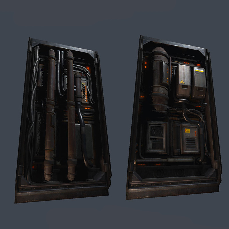
Basically (if I got you right and from the looks of the Box), the Author essentially has the same basic box and assets in it in both images.
If you look carefully, you'll see that the tubes in the first image on the left are big, but on the second one (right) they're downscaled.
Also, notice the rubber pipe on how on the left is almost rigid and is huge, yet on the right it has been bended, and there is even slight stretching near the middle.
So basically, what I got from all this is that having a solid planned base (the box) and generic assets in it, you can add and remove pieces as you please.
Take what I said with a grain of salt mind you...I'm just guessing what the question is here.
You can go about that way by re-using the same assets within that asset and scaling them, rotating them, modifying parts of it differently.
One thing I forgot to mention is that in the image supplied, the electric box in the two different shots with different modules inside can easily be put on one texture page. You wouldn't necessarily need two different material id's for it. Unless of course you're using a different texture from another asset that you wanted to re-use, then you'd have two mat id's.
At least for me, I would have everything in that picture on one texture sheet, 512x512.
I will try and explain as good as possible here.
These two pieces are a couple of variations of a much larger sets. Some are techy "addon" panels like these ones, and some are more generic tiling metal plates only.
If I remember correctly this whole wall set is packed in a 1024x1024 texture, including the flat metal wall panels, borders and trims and all the techy stuff.
The previous replies here are correct, I did essentially make a few different tech pieces that I then rotate, flip around to create new variations. One of the smaller challenges for these ones were to still try and maintain some AO for the pieces inside, but still be able to create variations using the same textured parts.
If you remove the pipes and cords and just keep the basic fuse boxes etc, you could imagine that as being a flat texture where I've "extruded" the various boxes and such.
As others mentioned with the pipes and wires I simply had some sections in the texture with a part of a pipe, with normal map seams vertically and tiling horizontally, that way I could pretty much create any size of the pipe but still maintain the pixel density.
I hope that helped some. Let me know if you wonder anything else.
I am somewhat confused though...did you ever have to do overlapping uv's for the pipes and the cords? Could you elaborate more on this comment. "As others mentioned with the pipes and wires I simply had some sections in the texture with a part of a pipe, with normal map seams vertically and tiling horizontally, that way I could pretty much create any size of the pipe but still maintain the pixel density."
Also, I don't understand when you said its a packed texture are you saying there is no wasted uv space. I just don't see how you could extrude some of these objects like the electrical box and still keep the normal map information for edges and such.
Once again, take what I with massive truckloads of salt.
An object such a clean or slightly coppered metal can work very well with stretched UV's since in many cases, they won't rust or are coated, or hell, the could be even polished with a grinder and that things in industrial never leave ANYTHING really polished. They almost have a Zulu like scratch on them, so that could also work if you're detailing.
So playing with dark muddy colors like Philip has, you can leave them be, or simply go into the UV editor, and as Maxim said, relax them, although I would do it manually (EI: shrink the backpanel of the extrude so the sides of the panel cover the a good chunk of the texture I'm sampling from).
Truth be told, you could also stick another mesh ontop of the mesh you wish to change without the need for extruding, and if you engine supports realtime AO, then you're all set since AO really helps blend pieces together (EI: Static Meshes in UDK = lightmaps for the win), although that would be pointless since it kills performance ingame (the AO that is if it's realtime and the mesh needs to be an actor and not static).
Once again, I'm pretty sure a more versed veteran in this area will most likely prove me wrong.
Pretty much what Maxim and Ace-Angel said
Some smaller parts you could just get away with one smoothing group and just have some gradients in the normal map. But usually I try to avoid that to make the texture more reusable (sure it will cost a bit more vertexes as they will be split by hard edges then).
There are other ways you could do that tho by just manipulating the normals and still keep flat surfaces flat if you have them beveled. (thanks to peris for an awesome way of doing that (in maya tho))