maxscript idea - extrude surface expand

grand marshal polycounter
Hey all, another modeling workflow improvement I have been thinking of lately.
I find myself wanting to 'expand' the surface of polygon shells alot. By expand I mean, exactly the opposite to what a chamfer would perfom on the outer outline border.
Heres a diagram :
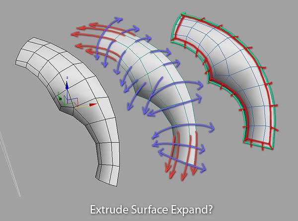
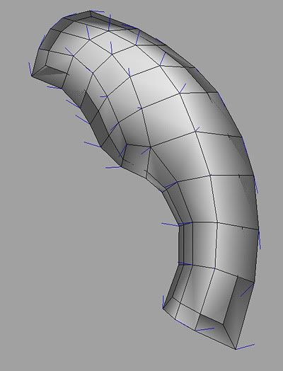
If I create an outline chanfer, then push it using CSslide, it gives the correct silhouette but a mess of folded shapes obviously :
One way I somehow manage to do it, is by using a convoluted workaround involving the shell modifier and move along normals... but it kinda sucks.

http://vimeo.com/7831268
Is there a better way to get such results? It sounds rather easy to script considering that CSslide and Shell seem to have all the core behavior needed for it ...
Please share!
I find myself wanting to 'expand' the surface of polygon shells alot. By expand I mean, exactly the opposite to what a chamfer would perfom on the outer outline border.
Heres a diagram :
If I create an outline chanfer, then push it using CSslide, it gives the correct silhouette but a mess of folded shapes obviously :
One way I somehow manage to do it, is by using a convoluted workaround involving the shell modifier and move along normals... but it kinda sucks.
http://vimeo.com/7831268
Is there a better way to get such results? It sounds rather easy to script considering that CSslide and Shell seem to have all the core behavior needed for it ...
Please share!
Replies
Failing that, I do something that's probably similar to your shell trick, but with extruding the faces that make up the border, then extruding the new faces that're now side-faced. Very messy, but you get a bit of control with the extrude dialog.
A proper script/tool for this would very handy.
The general behaviour should be something like this: select some border edges to expand. If there is no selection, expand the whole border. On first click or drag start defining the extension amount, on second click or drag shift the extended border along its normals to adjust surface "curvature" (in double quotes because surface curvature is a totally different subject, about continuity in nurbs surfaces).
p.s.
Have you tried latest IC.FrameIt 0.7b? Does it work as you wanted?
If that can be of any help, if you perform a chamfer on a border edge/outline the resulting edges all sit on that desired 'curved surface' so maybe you can get the new orientation from there (by finding the average between the newly created points of a double chamfer, or something!)
I like the idea, guess similar to spline > extrude or inset in editPoly/faces. except it works on edges like shift + edges selection drag.
this will not prevent you from overlaps and all that, which probably means you must try to detect this and run some relaxation on it. sometimes it can help to treat it as a 2d parameterization (think U,V, similar to how nurbs work)
In poly modeling you got only points in space, without any relation between them other than defining faces, and from faces defining edges. To preserve surface curvature is needed some sort of assumption, like surface is made of quads only, so you can jump from the extension point to some points over the surface and get the curvature angle that's preserved during extrusion.
I guess the easier solution is to extend surface by getting direction from proximal edges of each border vertex, handling the exceptions like a vertex between two edges sitting on a perfect line, then getting the extension amount from the user, and as last step let the user shift the new border along each new vertex normal (perpendicular to new surface lip in each point) to specify the new curvature. I think some tests are required.
Right now I'm cleaning up and finalizing IC.Shape 2.0 to be released in the next few days. I'll jump onto this as soon as possible.
I didnt mean someone drawing splines in max, but really deduce that info from analyzing the polys. maybe I didn't make myself clear there. anyway it's possible, and works rather fine, as many artists create relative good and smooth edge flows (I've successfully implemented similar before as plugin).
@deelekgolo, that script works by projecting vertices on a hi-res (or any reference) surface. therefore it can "slide" vertices on it. the problem presented here is "guessing" about such a reference surface that doesn't exist.
In other words : lets imagine that we perform an Extrude, or a simple Shell, on the edge of the base polygonal geometry. The resulting polygons go 'down' at a 90 degrees angles from the original surface. Now if you imagine the face normals of the newly created 'thick' edge .... they point in the correct direction wanted for the surface expand script. Then, the height/curvature of the newly created geo can be controlled with a later input in the script (or through a mere move along normals performed separately, like I did on the first connect shown in my video)
Hope this helps!!
Still messy as fuck though.
The idea is:
- Take the border vertex.
- Take the bisector of the angle formed by the edges along the border originating from the vertex.
- Take the vector normal to the surface originating from the vertex.
- Build the plane from the two vectors. It is perpendicular to the surface and intersects it.
- Get the intersection between the plane and surface edges (?)
- Build the spline from those points in space (?)
- Extend the spline from border end to find the final position for surface extension (?)
Using the intersection to build the spline avoids the assumptions of a specific type of geometry like quads only.
This is thinking out loud, I'm not sure of any of these steps. What do you have in mind?
@ Pior: If going flat is enough, I guess it can be done "quite" easily by tweaking the outline tool. Basically it should be something like: store current border vertexes positions, perform the outline, then cut the resulting surface following the position of stored ex-vertexes. Not trivial, but much easier. Again, after publishing IC.Shape, I'll be on this.
yes the sampling is indeed tricky, but what you describe sounds well. Basically walk the edges of the connected polys and check if the edge has either point on opposite sides of the plane, then intersect. Walk along the polys of those edges that did intersect.
or you assume quads/tris (which is what most people will work with) and pick vertices based on rules (faster). the benefit of following the natural edge flow is that you get smoother transitions into the "new surface".
after a little bit of tricky vector math, here is the first version of a new instrument. Get IC.ExtendSurface from IllusionCatalyst web site, under page IC.Tools. Please report any issue, as well as ideas for improvement. Enjoy!
As usual, evaluate once and find it under Customize User Interface... Category: IllusionCatalyst Tools.
Thx
Only issue I have with it personally, is once you edit the angle with CTRL and release it, the movement doesn't work as I'd expect/like. It would be nice to have an option (alt+ maybe?) for it to move back along the edge constraint. It would be very handy, if you ended up extruding too much.
That direction still needs to be averaged by the previous neighbor's edge direction to define curve?
not jes "normal" direction alone ( not just straight? ).
Store that curve position for offset like u described, so new correct normal direction is stored.
rape dis here script:
cly_gestureSmoothing.mel ( sorry mel.. but the math should iz there )
Gesture Smoothing reaches the limit surface by using the direction of geometry before the quadrilateral divisions. The average between the vrt being calculated for and the direction vector extents, describe gesture continuity.
And btw if you want that "energy preserved" subdivision in Max ... it simply is the Tesselation modifier. Easy!
right now the script set the surface extension "straight" from border, taking into account the proximal border faces. It doesn't follow surface curvature, but allow to tweak the extension slant.
@ mLichy: Thanks man, I see if I can push this a little further.
@ Vassago: I'm afraid I cannot understand exactly what you mean. The scripts does all its math to collect extension vectors for each selected border vertex, then create the geometry to tweak. By dragging without pressing any modifier key, it changes the extension amount. When you press CTRL and drag, extended lip just revolve around extension border, like a hinge. When you drag again, after changing the extension angle, the direction is still the one you got at the beginning, it is not recalculated, and so it doesn't appear to extend "straight" anymore. Is this the issue you're referring to? If not, could you please elaborate on this?
@ Claydough: Thank you for your offer, but I think this is another set of problems. In a closed mesh there are different assumption that can be done, and geometry doesn't have to be guessed. The only solution I could think about, is the one I shown in a previous post, by getting the intersection of a virtual plane to the surface and then building a rail spline. Unfortunately is not that simple to code, and I'm neither sure it would lead to good results.
@ pior: Is this solution similar to what you got in mind when posted the original idea?
Now if there ever was another function to add ... that would be a way to somehow load a spline path as a way to define the successive extensions, with overall length and angle user-defined just the way they are now.
For instance one could make a cool extension and manually extract a linear spline form the resulting mesh ; then, running 'extendsurfacespline' would popup a dialog to pick the desired spline profile to work from. This would allow for easy copy/pasting of a specific extension look - somehow like the shell modifier does, but better!
Lemme know if you are interested ; if so I'll mock it up for you in images. It might require a menu with spinners for x y z and scale, plus an option to invert the spline - which is okay since copying-pasting such a spline profile is more of a uniue operation as opposed to the regular surface expand which is more of a freeform modelling tool, best used interface-free.
Also modifier stack structure (plugin only?) is not necessary since I believe it would be very easy to just start over again to change the extension look, if the spline pasting works.
Just to be sure you know this, you can already extend limited portions of borders too, not the whole necessarily. So if you want the same extension in two or more different positions of the same object, just make two separate selections and run the tool.
p.s.
Thanks for the nice screenshots! Right now I'm struggling to make some simple videos work on my web site. I hate everything related to html
I just release an updated version of IC.ExtendSurface 0.2. It now handles extension slant much better, even if it is still not perfect, feels like a good improvement. As usual, get it from IllusionCatalyst web site. Please let me know how it works and report any issue. Thanks.
@ Pior: This is not the big upgrade you asked. I think it should be a completely different tool. It looks to me much more like a 1-Sweep Rail (as is called by Rinoceros3D). A set of tools I'd like to code is about these nurbs-like tools. I think your idea fits better in that set.
@ Vassago: I'm sorry, but I couldn't understand what you meant. Please try this updated version and tell me if is better for you. Thanks.
Get IC.ExtendSurface 0.2.
i got one little issue though and i'm not sure whats causing or if other people are having similar problem. i'm one of those minority that uses a wacom 100% of the time in Max and alot of the time with the script i'm having an issue with "left click to start another extension". sometimes it seams to work and sometimes it doesn't. i'm not sure if its to do with the pen perssure or something else. with a mouse the left click to start another extension works fine, its just with the wacom.
i tested in max 2010 x64 (all service packs and hotfixes) & 2011 x64 on xp64 with a wacom intuos 3 with latest drivers.
just wondering if anyone else that uses a wacom has this issue?
thanks for any help
***EDIT*** i figured out that i have the wacom perfectly still and then tap it with out moving to start another extension. maybe it would be cool to add shift or alt to extend the edge and then ctrl for changing the angle or is this a bad idea?
I planned to revise and tweak this tool before the integration into IC.Shape.
The tool is super handy, I use it alot :P If you want to improve on the functionality further, there might be things to try regarding the case of an extension going 'in', eventually collapsing on itself with edges intersecting each other. Maybe in such case, make everything go to a point instead. I usually commit the tool and merge everything to center, but there might be cleaner ways to avoid that. Maybe capping the whole thing as a perfectly round Ngon, with a nice quad flow to it (to avoid ending up with a 40-branched star for instance). Like, left click/ctrl drag to make extensions, then middle-clic to smart-cap the opening...
Anyways, fantastic tool !!
Thanks
Not working with max 2012. i think that is why Enrico took the script from his website
Just sayan.
Cheers
Once the installation is done, you can find it in the customization menu of 3ds Max. From the main menu choose:
Customize > Customize User Interface...
In the dialog choose the Tab relative to the kind of action you want to define to run the Extend Surface script: Keyboard shortcut, button in a Toolbar and so on.
In the panel find a drop down menu called Category, open it and select IllusionCatalyst Tools.
The list Actions gets populated with the Extend Surface script. Depending on the kind of action (Tab) you chose, you can assign a Keyboard shortcut, or drag and drop the name of the script over a Toolbar to create a new button.
Once done, close the dialog.
Create an Editable Poly object, select a border and run the script through the shortcut or the button just made.
The Max UI is automatically saved on close.
For further information please visit the IllusionCatalyst website.
Cheers
- In the Customization dialog go to the Toolbars tab.
- Find the Category: IllusionCatalyst Tools.
- Click on the Extend Surface action and drag it to the Main toolbar on top the viewports, it will create a button for you.
- Close the customization dialog.
- Create an Editable Poly object, select some border edges and press the button you've just created.