Home Technical Talk

Cylindrical crap topology help

PrajnaParamita
polycounter lvl 6
Offline / Send Message
Pinned
PrajnaParamita polycounter lvl 6
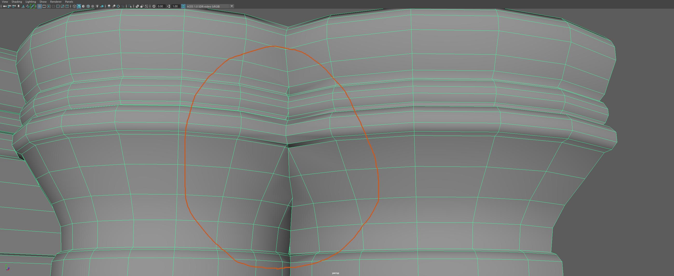
Hi, i have recently got back into 3d modelling, how would i go about fixing the topology of these booleaned cylindrical columns, i want to keep the edges of the columns so the maintain their shape, would i have to add extra edge loops? curious as to suggestions or whether the problem is in how i went about modelling them in the first place. many thanks
Replies

  • Benjammin
    Offline / Send Message
    Benjammin greentooth
    Rotate the individual columns so the topology lines up as best you can at the seam to minimize cleanup. Then cleanup, because there's always cleanup in boolean ops. Finally, add a bevel or hard edge at the seam.
  • PrajnaParamita
    Offline / Send Message
    PrajnaParamita polycounter lvl 6
    Benjammin said:
    Rotate the individual columns so the topology lines up as best you can at the seam to minimize cleanup. Then cleanup, because there's always cleanup in boolean ops. Finally, add a bevel or hard edge at the seam.

    Just to add the one on the left is smaller in circumference to the one on the right, any tips on how i can remedy the pinching? at this point i am thinking of starting the columns again from scratch :|
  • Alex_J
    Offline / Send Message
    Alex_J grand marshal polycounter
    what is the reference? 
  • PrajnaParamita
    Offline / Send Message
    PrajnaParamita polycounter lvl 6
    Alex_J said:
    what is the reference? 
    Hi, here is the geometry I am trying to replicate, the original doesn’t flute out at the top of the central columns but for my own take on it I wanted the central bits to flute out and merge together
  • Alex_J
    Offline / Send Message
    Alex_J grand marshal polycounter
    gotcha so it is a large architectural piece? And made of concrete or stone or something like that?

    If that is the case my first instinct would be to not merge them at all, rather leave the columns as individual units that can be used in a modular way
    but if you have to merge them do like benjamin said and perhaps increase the width of the connecting faces inbetween. for the cleanup with that one edge i think you could run it up to the top corner
    i'd look for real life reference for this sort of construction and pay special attention to how pieces like this are merged. my guess is that it's probably a  pretty large and smoother transition and if you modeled it that way, would be less issues.
  • PrajnaParamita
    Offline / Send Message
    PrajnaParamita polycounter lvl 6
    Alex_J said:
    gotcha so it is a large architectural piece? And made of concrete or stone or something like that?

    If that is the case my first instinct would be to not merge them at all, rather leave the columns as individual units that can be used in a modular way
    but if you have to merge them do like benjamin said and perhaps increase the width of the connecting faces inbetween. for the cleanup with that one edge i think you could run it up to the top corner
    i'd look for real life reference for this sort of construction and pay special attention to how pieces like this are merged. my guess is that it's probably a  pretty large and smoother transition and if you modeled it that way, would be less issues.

    many thanks for the feedback, i would like to try keeping them merged (as from what i have seen from other references of this column they are, at least in this section,molded) first before resorting to leaving them individual, would you suggest just sliding the connecting edges of the faces that meet on the smaller of the two columns so it meets up or increasing the scale of the whole upper fluted bit? again many thanks for the info :)
  • Alex_J
    Offline / Send Message
    Alex_J grand marshal polycounter
    either way might work but should probably get the model in your rendering engine with some basic textures, that way you can see what effect those changes would have on the final product. For example if you have one less edgeloop to hold the shape of the cylinder it might look bad once you have real lighting applied. Or maybe it does not make a difference. If you made the top part larger maybe it causes some problems elsewhere. Or not. You just have to test it out to see. 

    Remember that the topology is means to an end, not the end itself. So it's help to get to the end quickly and then you can identify where problems are, go back and fix them, export the model again with changes and test again. It is usually faster and ends up with higher quality to use an iterative approach like this, rather than trying to get everything perfect in one swoop.
  • gnoop
    Offline / Send Message
    gnoop sublime tool
    I usually just keep separate columns , do copies , do boolean union of them   , make vertex auto merge by small distance  to weed off redundant vertexes , make the intersecting edge split  , then  transfer  normals  from original  columns to each split mesh  accordingly .     No shading  artifacts at all .  Done.  Always perfect shading  even if you happen to keep a rat nest  of messed triangles there accidentally .     

    So much easier  than solving all those topology puzzles.  Could be done non destructively  by geometry nodes and a few data transfer modifiers on top of it  .    Not sure why people still  torture yourselves with "proper" topology .  To get nice subdiv?   But what for ?    For smoother cylinders in zbrush  you can subdiv the original ones before boolean union  .


  • okidoki
    Offline / Send Message
    okidoki greentooth
    Maybe it's an idea to model this by using the a segmented part of the pillar and then using some mirror modifier which use clipping at the mirror axis like so: 


    With this there is no overlapping and the non-mirrored part could even be used as  a module..

Sign In or Register to comment.