Home Technical Talk

Shading issue...

polycounter lvl 9
Offline / Send Message
Ladytron polycounter lvl 9
Hi.
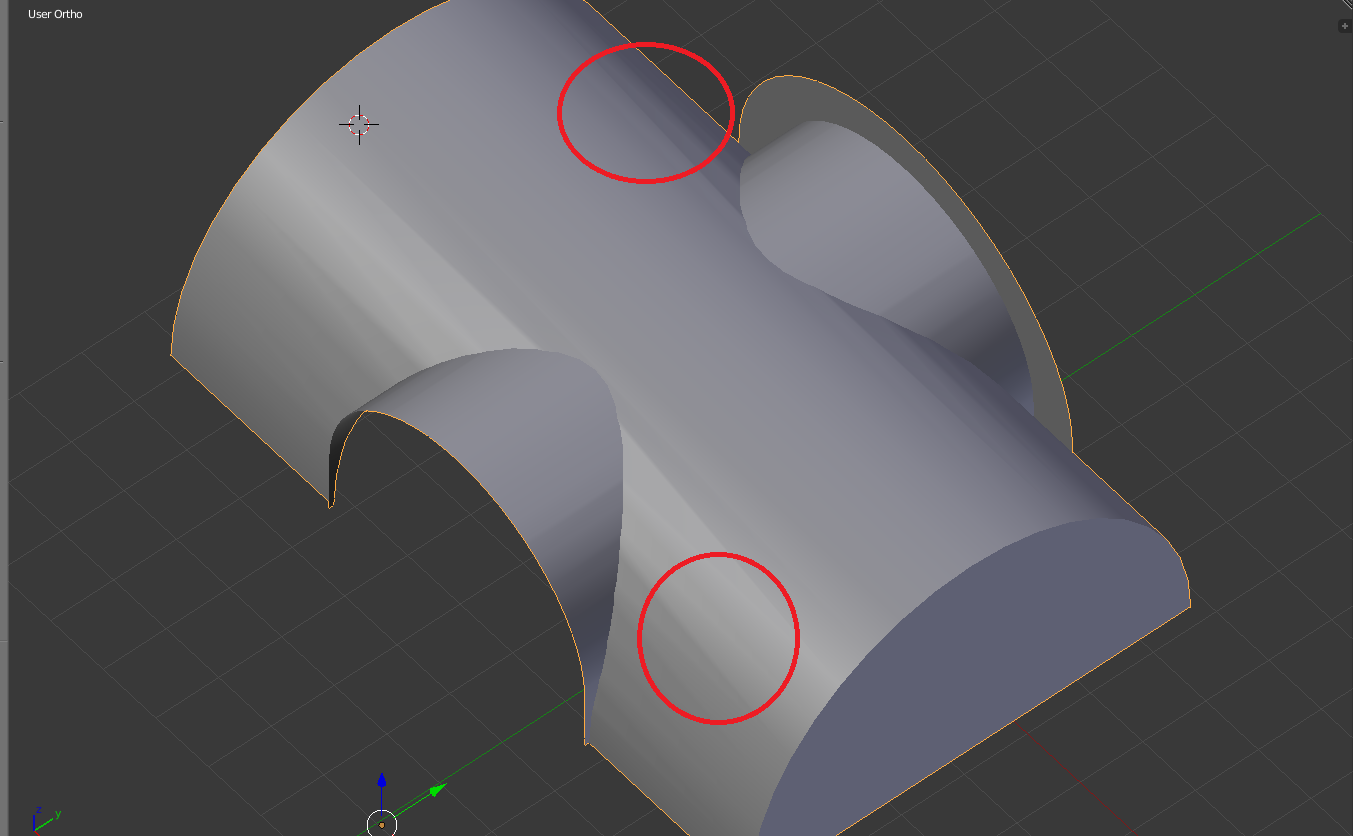
I'm having an issue with smooth shading. I'm using Blender 2.76.
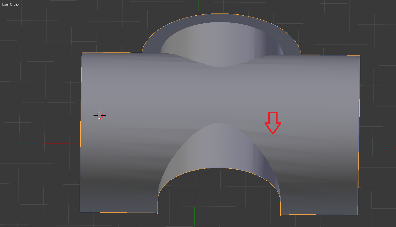


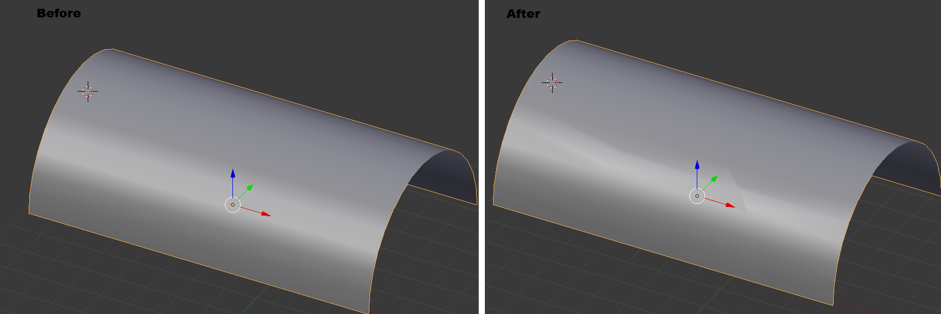
As you can see from the photo, the shading isn't smooth. There are lines showing. I've tried to bevel the edges but that didn't fix the shading. I did use Knife Project on the sides and that seems to be when the shading messes up. Also, I'm using Auto Smooth.

Here is how it looks before/after using Knife Project. 


If anyone know how to fix this, I'd appreciate the help.

Thank you!  <3


Replies

  • Kanni3d
    Offline / Send Message
    Kanni3d ngon master
    Show us your wireframes? Likely has to do with the two intersecting cylinders segments not lining up. If even if they are an even amount perfectly and are welded/lined up, the curvature of the cylinder could ruined the moment you move/weld things out of place, giving you those shading artifacts.
  • gnoop
    Offline / Send Message
    gnoop sublime tool
    There is two approaches  for such issues. 

    a) Making edges meat each other in intersection line  Plus  extra edge loops  right/left of intersection line . 

    b)  By working with vertex normals  only  with whatever actual tessellation  where you can use data transfer modifier  to project /borrow/ suck in  normals from each of two  initial cylinders ( subdivided for perfectly cylindrical shape) to respective parts  of your model . Intersection line should be split so  edge vertexes  wouldn't  have shared normal .   You can merge vertexes later  but still have to mark intersection edge loop split ( cyan colored)

    If you want to use subdivision  with this second method you need to check in "custom normals"  in subdivision modifier   and be carefull with extra editing   since any new loop could  modify transferred normals and you would have to do it again.


  • Ladytron
    Offline / Send Message
    Ladytron polycounter lvl 9
    Thank you guys for the replies @Kanni3d and @gnoop<3

    So I think I understand what you guys are saying to do, maybe I'm wrong. I used the knife tool to make edges...


    ... but it didn't fix the issue. You can still see lines. 


    I'm not really comprehending the second method you mentioned @gnoop. :( 
  • Kanni3d
    Offline / Send Message
    Kanni3d ngon master
    Yeah, judging from the wireframe:
    • too many edges
    • edges/cylinder segments on the inare not evenly spaced, ruining the curvature already
    • edges are not lining up with the perpendicular cylinder edges
    Depending what this mesh is used for (offline rendering? game art? highpoly/sub-d model to be baked down?), just start with a really low amount of segments. This will ensure it's much easier to manage merging the two together, and easier to control the shading.

    In essence, this issue you have is just due to way too many erratic segments, which are then smashed together.


    Preparing the two meshes to be welded/booleaned/merged together, ensuring the segments are low and manageable, and line up


    Booleaned together, no stray vertices, edges are straight and preserve the cylinders curvature


    Added additional holding edges/support loops for sub-division.

  • gnoop
    Offline / Send Message
    gnoop sublime tool
    I'm not really comprehending the second method you mentioned @gnoop. :( 
    Shading of polygons  in 3d graphic is being defined by vertex normals . Its inclination  to surface . https://en.wikipedia.org/wiki/Vertex_normal
    Typically  Blender calculate/set vertex normals automatically   by polygon/edge flow . Thus   you do those support loops and regular tessellation to help 3d package set vertex normals right in automatic  manner.   

    3d package is stupid like rock really and have no AI  to figure out  on its own  that a cylinder shouldn't have any  shading odds  ( why still not in 2021 I am not sure)    so you do those "right" tessellation and redundant edge lopps  with only purpose to help the soft to do it right.

    The second method is  not helping  3d package  to set it right through edge/polygon flow  but rather  by setting  those vertex normals  directly/ explicitly    whatever  crazy  underlying  polygon  flow or edge loops might be .      Such vertex normals are called "custom normals"  in Blender  and "explisit"  normals  in 3d max .

    If you couldn't allow all the extra geometry/ edge loops   to make it right automatically  ( in mobile games for example)    it's sometimes  simpler and quicker to just  rotate those normals to their right positions  manually  or  "borrow"/ transfer / project   them from another piece of geometry where the shading is perfect already.     Data transfer modifier in Blender , attribute transfer in Maya , or normal theft script  for 3d max   do that.


  • sacboi
    Offline / Send Message
    sacboi high dynamic range
    Curious, if there's a specific reason for generating longitudinal manual cuts on a curved surface using the knife tool, combined with auto smoothing the mesh?
Sign In or Register to comment.