File Format Compressing Faces?
Hey all! so I'm making a set of mod tools for a couple of video games as the tools are either non existent or outdated and no longer work on modern systems.
I'm starting off with a simple converter for the game's model files that will convert them to Wavefront OBJ and then back again.
These are proprietary file formats based off of the old .QOB file format, however they are not the same.
Just a note: This is my first time taking on a project such as this so I apologise if there's something i've missed or if I sound a bit 'nooby'
I've been able to get the converter dumping the correct vertex positions into an OBJ file and I've verified this. However the faces are a little odd/tricky.
I'm testing the converter for one of the file formats on a small sample model which i have access to, and this model is expected to have 30 triangular faces and 28 vertices.
However with the face section of the model, it is impossible for it to have this many faces without some kind of compression/math being applied either on the engine or rendering API level.
The face section is 96 bytes long. With a byte in the geometry properties section of the file stating that the face section length is actually only half that size, at 48 bytes.
Each vertex index definition for the face takes up 2 bytes alone.
Assuming we're dealing with Triangular faces here with no other properties such as normal and UV indices, that gives us a possibility for either 16 faces (assuming a 96 byte section length) or 8 Faces (assuming a 48 byte section length)
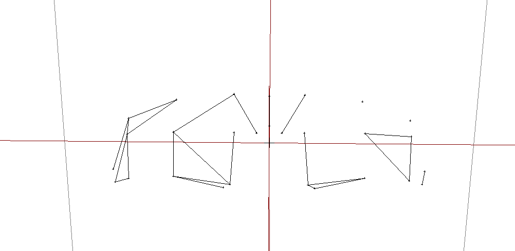
Furthermore, spitting these indices into a face section of an OBJ file gives me the following:
f 1 2 3
f 4 5 6
f 7 8 8
f 9 9 10
f 11 10 12
f 13 14 15
f 16 16 17
f 17 14 18
f 12 19 12
f 20 11 20
f 21 19 21
f 22 23 22
f 24 25 24
f 26 2 26
which gives me this when I verify:

The duplication of vertex indices indicates to me that I'm doing something wrong here.
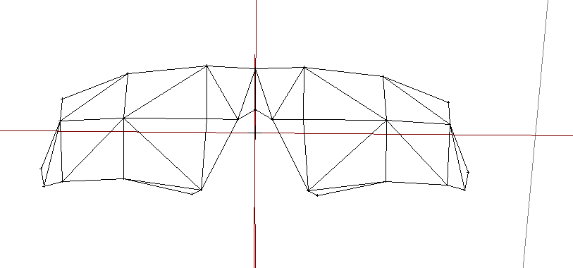
I manually reconstructed the face section and this is what I got:
f 1 2 3
f 2 24 26
f 4 5 6
f 4 27 25
f 4 2 26
f 4 3 2
f 4 3 5
f 6 27 28
f 6 27 4
f 7 6 5
f 8 7 6
f 9 10 11
f 11 10 12
f 13 14 15
f 15 16 14
f 17 14 18
f 12 18 14
f 12 10 13
f 12 13 14
f 18 12 19
f 12 19 20
f 20 11 12
f 20 21 11
f 21 19 20
f 22 21 19
f 21 23 22
f 24 22 23
f 24 25 22
f 24 25 26
f 25 26 4
which gives me:

I've got the original file with some information I've pulled about the file format if needed.
Has anyone seen something like this before? can anyone advise on what else to try? I'm particularly curious about it giving a 48 byte section length as opposed to 96, as in other, larger models it gives the correct section length.
Any help will be appreciated on this side!
I'm starting off with a simple converter for the game's model files that will convert them to Wavefront OBJ and then back again.
These are proprietary file formats based off of the old .QOB file format, however they are not the same.
Just a note: This is my first time taking on a project such as this so I apologise if there's something i've missed or if I sound a bit 'nooby'
I've been able to get the converter dumping the correct vertex positions into an OBJ file and I've verified this. However the faces are a little odd/tricky.
I'm testing the converter for one of the file formats on a small sample model which i have access to, and this model is expected to have 30 triangular faces and 28 vertices.
However with the face section of the model, it is impossible for it to have this many faces without some kind of compression/math being applied either on the engine or rendering API level.
The face section is 96 bytes long. With a byte in the geometry properties section of the file stating that the face section length is actually only half that size, at 48 bytes.
Each vertex index definition for the face takes up 2 bytes alone.
Assuming we're dealing with Triangular faces here with no other properties such as normal and UV indices, that gives us a possibility for either 16 faces (assuming a 96 byte section length) or 8 Faces (assuming a 48 byte section length)
Furthermore, spitting these indices into a face section of an OBJ file gives me the following:
f 1 2 3
f 4 5 6
f 7 8 8
f 9 9 10
f 11 10 12
f 13 14 15
f 16 16 17
f 17 14 18
f 12 19 12
f 20 11 20
f 21 19 21
f 22 23 22
f 24 25 24
f 26 2 26
which gives me this when I verify:

The duplication of vertex indices indicates to me that I'm doing something wrong here.
I manually reconstructed the face section and this is what I got:
f 1 2 3
f 2 24 26
f 4 5 6
f 4 27 25
f 4 2 26
f 4 3 2
f 4 3 5
f 6 27 28
f 6 27 4
f 7 6 5
f 8 7 6
f 9 10 11
f 11 10 12
f 13 14 15
f 15 16 14
f 17 14 18
f 12 18 14
f 12 10 13
f 12 13 14
f 18 12 19
f 12 19 20
f 20 11 12
f 20 21 11
f 21 19 20
f 22 21 19
f 21 23 22
f 24 22 23
f 24 25 22
f 24 25 26
f 25 26 4
which gives me:

I've got the original file with some information I've pulled about the file format if needed.
Has anyone seen something like this before? can anyone advise on what else to try? I'm particularly curious about it giving a 48 byte section length as opposed to 96, as in other, larger models it gives the correct section length.
Any help will be appreciated on this side!
Replies
You only need 2 verts to define a mid strip Tri if that's the case and might explain the funny numbers.
https://drive.google.com/file/d/127FzMskJjBRH6Ga5QvHzmkFNVHRK-PfJ/view?usp=sharing
I'll get the data types and file information for you shortly.
Interesting, I thought it may have been defining something similar, I thought it was possibly defining edges though, lol! is there any more information on Tri-stripping and how to program my software to calculate the correct faces anywhere?
Hopefully the formatting doesn't bork
XQOB File
Header Size – 16 Bytes
File Structure:
MEMB
MTRL
GEOM
MESH
SLIT
MDLT
PHYS
MODL
XCHR (XSKA only)
File Header
Location
Length
Type
Description
Value
0
4
Unsigned int
File Length
Variable
4-7
4
String/Date
XQOB File Header – Contains Date
XQOB - 04/03/2005 02:13:44
2
4
Unsigned Int
Mesh Count
Usually 2, Sometimes 3
Texture
Location
Length
Type
Description
Value
TXTR+1
4
Unsigned Int
Texture Index 1
1
TXTR+4
4
Unsigned Int
Texture 1 Size
512
TXTR+5
4
Unsigned Int
Texture Index 2
2
TXTR+8
4
Unsigned Int
Texture 2 Size
512
TXTR+9
4
Unsigned Int
TextureCount
Typically, 2
16
4
Unsigned Int
Section Size for TextureList (In bytes)
Variable
36
4
Unsigned Int
Texture 1 Name Length (Bytes)
Variable
Variable
4
Unsigned Int
Subsequent Texture Name Lengths occur immediately after Preceding texture name
Variable
Member
Location
Length
Type
Description
Value
MEMB-4
4
Unsigned Int
Section Length
Variable
MEMB-8
4
Unsigned Int
123456
MEMB+1
4
Unsigned Int
Object Count
Variable
MEMB+24
4
Unsigned Int
Vertex section length
MEMB+80
4
float
First vertex position
variable
MEMB+Vertexes
2
Ushort
Face vertex indices
variable
XQOB File Bytes Per Vertex: 24
XSKA File Bytes Per Vertex: 48
Material
Location
Length
Type
Description
Value
MTRL-4
4
Unsigned Int
Section Length
Variable
MTRL+1
4
Unsigned Int
Illumination Model
Typically, 2
MTRL+9
16
Unsigned Int
Material header
Variable
MTRL+24
80
Variable
Material parameters
Variable
MTRL+104
36
Unsigned Int
Material Signature
Variable
Geometry
Location
Length
Type
Description
Value
GEOM-4
4
Unsigned Int
Section Length
Multiples of 76 depending on number of elements
GEOM+17
4
Unsigned Int
Vertex Section Length 1 – this is 0 if there is only one object
Variable
GEOM+25
4
Unsigned Int
Face Section 1 length
Variable
GEOM + 92
4
Unsigned Int
Vertex Section 1 + Face Section 1 + Vertex Section 2
Variable
GEOM + 101
4
Unsigned Int
Face Section 2 length + 1
Variable
GEOM+9
2
Unsigned Short
Object 1 Vertex Count
Variable
Mesh
Location
Length
Type
Description
Value
MESH-4
4
Unsigned Int
Section Length
Variable
SLIT
Location
Length
Type
Description
Value
SLIT-4
4
Unsigned Int
Section Length
Variable
MDLT – Possible UVW definitions
Location
Length
Type
Description
Value
MDLT-4
4
Unsigned Int
Section Length
Variable
Physics
Location
Length
Type
Description
Value
PHYS-4
4
Unsigned Int
Section Length
Variable
MODL
Location
Length
Type
Description
Value
MODL-4
4
Unsigned Int
Section Length
Variable
MODL+4
4
Unsigned Int
256
MODL+12
4
Unsigned Int
-256
XCHR – Skeleton & Weights Definition
Location
Length
Type
Description
Value
XCHR-4
4
Unsigned Int
Section Length
Variable
Vertices and Faces are in the MEMB section, the first vertex starts 80 bytes after the 'MEMB' string, then the faces start immediately after the vertices. GEOM and MESH are just properties sections.
the raw data suggest first five faces would be...
1 2 3
4 5 6
7 7 8
8 9 10
9 11 12
that's one bad "chunk" file implementation..... the point of the doom chunk file format is the sizeof chunk in bytes (4 bytes after the 4 byte tag) takes you directly to the start of the next chunk tag without fail.
so each tag is 16 bytes long... so something like
<int, int, int(tag data length after tag), 4 char code tag>
can't think of any reason they would want to compress the face indices
so the indice
12345678...
mean
faces
123
234
345
456
etc
the duplications are a way of continuing the strip without the face being visible
so it's visible with wireframe
but not without
obviously you need to solve the ordering issue .... could be alternating
You're Awesome!
is there a specific algorithm I need to use?
also the 4 bytes after
MEMB+24
4
Unsigned Int
Vertex section length
is the number of face indices (if you didn't know already)