How to avoid "separated" or "black" edges on model using a heightmap?
I created a heightmap for my model by two different ways: in photoshop, and with a program call Materialize, and both gave me the same results. This is my first time using heightmaps, so I'm definitely missing something. I'm trying to use it (the heightmap) in Unity with the Standard Shader, however, I've seen some videos that use heightmaps on Unity and they didn't seem to have these issues.
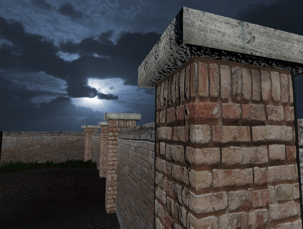
This is how it looks with the Standard Shader:

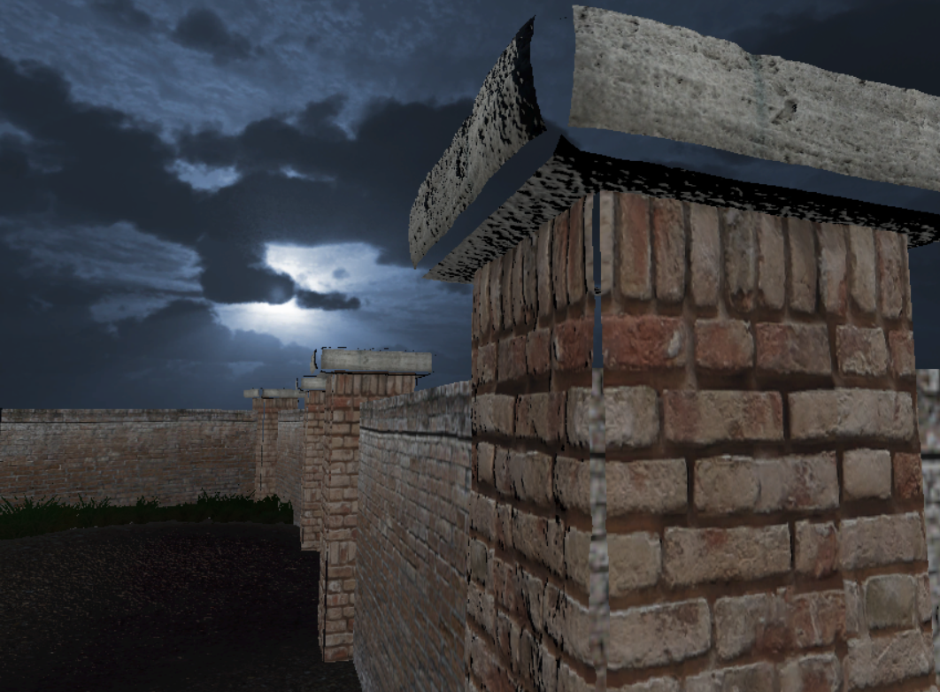
Changing the Heightmap value on the shader throws me this result, those black bars on the edges. Materialize offers a shader for Unity, so I tried to use it, and it gave me this results:

So yep, nothing beautiful as you can see. I've read on a post on StackOverflow that you could weld the edges to avoid this issue, and also I read on Unity Answers that sometimes you would need to flatten the edges on the heightmap.
That lead me to the conclusion that maybe this isn't a shader issue, but rather a model/texture issue.
So, what can I do to avoid this?
I used Blender 2.9 to make that prop (the brick pillar).
This is how it looks with the Standard Shader:

Changing the Heightmap value on the shader throws me this result, those black bars on the edges. Materialize offers a shader for Unity, so I tried to use it, and it gave me this results:

So yep, nothing beautiful as you can see. I've read on a post on StackOverflow that you could weld the edges to avoid this issue, and also I read on Unity Answers that sometimes you would need to flatten the edges on the heightmap.
That lead me to the conclusion that maybe this isn't a shader issue, but rather a model/texture issue.
So, what can I do to avoid this?
I used Blender 2.9 to make that prop (the brick pillar).

Replies
if OP can post his uv's, it may help spot something, otherwise I'm leaning more towards an issue with the shader or material setup.
And this is my heightmap (I edited the edges of the image, but it didn't make any difference):
Probably as you can see I don't know anymore what I'm doing xd
As I investigated, it seems that what you've said it's definitely the way to go, but I'm a bit lost...
So first, as you said, I made a small bevel along the edges of the original model. Now, it seems that Smooth Group/Shading does not exists as it is in Blender, but there are a few ways to achieve something similar, or I read so (I created a vertex group and the applied a modifier called Smooth). This is the post I saw on StackOverflow, I followed the second answer: https://blender.stackexchange.com/questions/4806/blenders-smoothing-groups-solution-edge-split-destroys-topology-is-there-a
Now, before doing anything else, I exported the model and went back to Unity, and...it happened pretty much the same. So I headed back to Blender and, with faces selected, I used Face->Weight->Normalize All.
It also didn't work, so I gotta admit that I need some more guidance...