The BRAWL² Tournament Challenge has been announced!
It starts May 12, and ends Oct 17. Let's see what you got!
https://polycount.com/discussion/237047/the-brawl²-tournament
It starts May 12, and ends Oct 17. Let's see what you got!
https://polycount.com/discussion/237047/the-brawl²-tournament
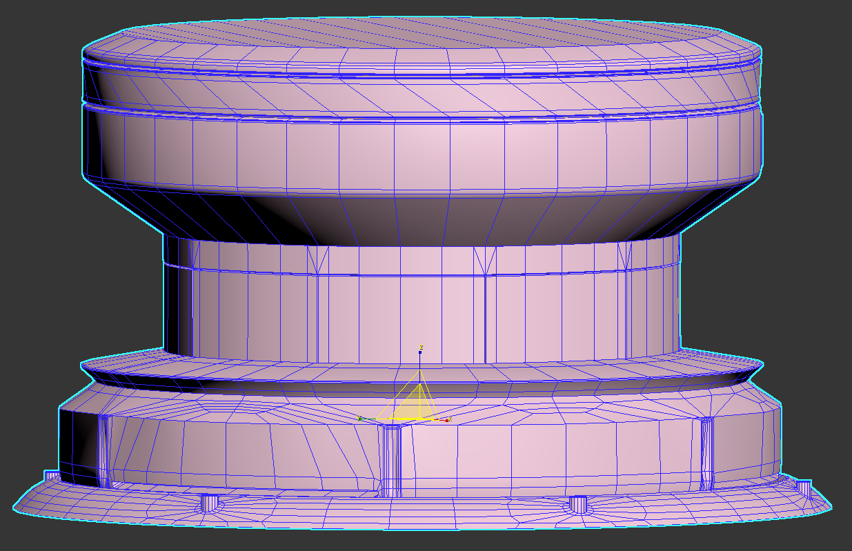
Is this bad topology? Gustavo_Elliott
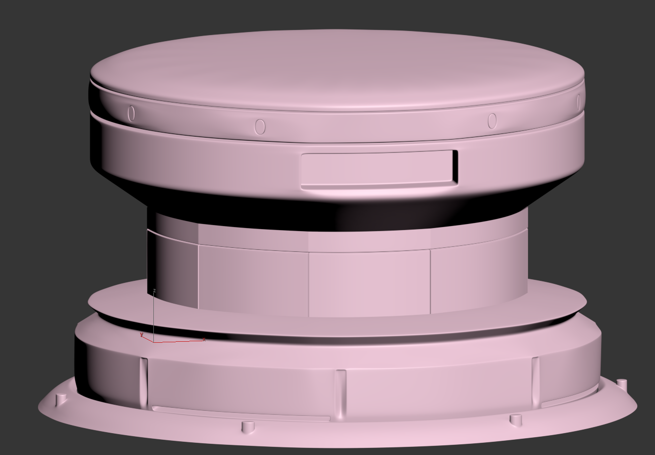
I'm participating in the environment art challenge and am coming up on topology issues while making my low-polys. Is the topology on this cylinder as bad as I think it is? I know there are a few more obvious edge loops that can be taken out but the part that bothers me is the rectangular detail near the bottom. Thanks in advance.


Replies
Hee there! I did try to photoshop some issues in your model to explain it the best way I can :P. There are multiple techniques and ways to model I just explain what I should do in your situation. First of all number 1, it seems like the edges got a twists and are not using straight lines. Not that big of an issue but it can be an issue if you want to modifie it in a later stadium or want to extrude or adjust things. Number 2. all these green dots are floating vertices they create N-gons. The can make it an issue in a later stadium like texturing or using other software for your model. Also its not really clean, try to avoid these! number 3, these are a lot of edges! and they basically doing nothing, it looks like you've smoothen the object once and now try to delete edges. Try to use the seme amount of segments each part of the model. This way you well get better and straight lines between the different parts of the model. Kinda hard to explain everything, hope I could help you out a bit. Tip when you are creating objects in cylinder shape is to keep the amount of segments the same on the whole model (if possible). Good luck! oh and cool object btw
You should break apart objects that wouldn't normally be connected. It makes it a lot easier to work on.
In the real world you wouldn't machine this out of a solid block, so don't try and model it as one solid chunk. Working on each piece is easier and you don't have to worry about your edges flowing into other areas.
So for example the studs around the bottom of your model. They look like they are part of the main mesh, it mushes and smooths like was vacuum formed and maybe that is what you're going for? But in reality that is a hard shape to make and only a handful of materials and techniques can do it. Plus what is the point? Decorative cover that fits over the top of something else?
It would probably be a hole in the main mesh and a separate pin attachment ring, that holds the main part in place?
A bit like a hood clamp.
Now you don't have to worry about cutting a hole in the main mesh, you just need to model a hood clamp and place it over the top of your mesh. No messy edges, no crazy topology flowing across two separate things, just cool details.
I'm not sure why the top is rotated and I'm not sure why it bothers me so much but I just want to grab those top verts and rotate it back so the edges are straight, lol. They could also be separate objects...
This gives a little more clarity to my recent struggles, I should have posted a pic showing them all as different elements before as well. I'm attempting to work from this concept for the monthly environment art challenge. but I rotated those verts that were bothering you XD. I'll clean up the flow a bit later. The part highlighted in red is what bothers me the most. As for the studs at the bottom, instead of trying to extrude those shapes out you're recommending I model just the studs and place them on top? Should I use something like JokerMartini's welder script for some more realism?
Should be a near seemless transition