Learning trim sheets. Some questions...
Hey guys. New to trim sheets and I've been experimenting tonight with Morten Olsens guide (https://www.gdcvault.com/play/1022324/The-Ultimate-Trim-Texturing-Techniques). Figure I'd throw all my issues and questions into this thread, hoping to get things cleared up:
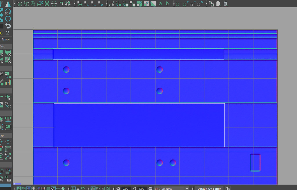
To get my 45 degree bevels, I tried taking a cube in Maya and applying a single segment bevel to it. I made about 4-5 different size rectangles and laid them out on a 1x1 plane, trying to match Mortens trim sheet just for practice (my example below). I deleted the under part of the cube since I only need the top face and the bevel. I then baked these down in substance painter to a 1x1 plane and applied a simple plastic material to it.
Back in Maya, I created a test mesh. I did a quick auto unwrap to get even texel density for the test mesh, then started to lay out my faces on the trim sheet. I tried my best to eye the UVs to line up to the edge of the normals on my trim sheet. Though this does not seem to be the correct way to do this and I'm not sure what is.

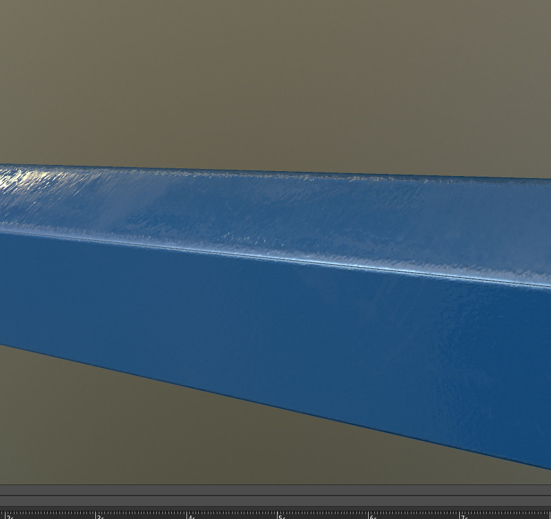
but I ended up getting poor results with obvious seams:

What am I doing wrong here? Also, I find myself having to stretch some UV shells to match the trim sheet. I suppose for tiling textures some minor stretching isn't a big deal, but should I be doing this? Am I missing something here?
Also, I always read that trim sheets tile left to right/right to left - but this technique does not. It's only as wide as the trim sheet itself since there are bevels on the sides as well. Very confused.
Please help me understand!
To get my 45 degree bevels, I tried taking a cube in Maya and applying a single segment bevel to it. I made about 4-5 different size rectangles and laid them out on a 1x1 plane, trying to match Mortens trim sheet just for practice (my example below). I deleted the under part of the cube since I only need the top face and the bevel. I then baked these down in substance painter to a 1x1 plane and applied a simple plastic material to it.
Back in Maya, I created a test mesh. I did a quick auto unwrap to get even texel density for the test mesh, then started to lay out my faces on the trim sheet. I tried my best to eye the UVs to line up to the edge of the normals on my trim sheet. Though this does not seem to be the correct way to do this and I'm not sure what is.

but I ended up getting poor results with obvious seams:

What am I doing wrong here? Also, I find myself having to stretch some UV shells to match the trim sheet. I suppose for tiling textures some minor stretching isn't a big deal, but should I be doing this? Am I missing something here?
Also, I always read that trim sheets tile left to right/right to left - but this technique does not. It's only as wide as the trim sheet itself since there are bevels on the sides as well. Very confused.
Please help me understand!
Replies
Also, the world space noise maps they used for colour variation etc. Will have masked a lot of distortion/sins.
Personally I don't think the system as described holds up to scrutiny these days - particularly not if we're looking at a PC fps or something.
For a 3pp game or anything where you don't get too near to hard corners I don't think you'll notice the seams.
The problems are fixable with the application of a bit of cunning and some Shader wizardry so I wouldn't dismiss the technique at all.
'floaties' - jacque choi 2015
It's cheaper to put cuts in the geometry than doing floaties. Floaties usually increase overdraw which is a bigger hit to frame rate than a few extra polygons.
Floaties are fine - if you have proper deferred decal shaders they look awesome and it really isn't that expensive. I have issue with using them widely for panel gaps and edge bevels or as detail on props but for isolated decals I'd say its usually worth it.
That said...
If you're using trim sheets then yes, cut the geometry in.
I sat down earlier with unreal and made this work with two UV channels after being reminded it was a thing. It obviously suffers the same issues on corners but you have a lot more flexibility in terms of laying out tiling maps for the materials. I expect there's more that can be done but I've opened a bottle of wine now so it isn't happening tonight..
Yours looks like it has no padding, butting up against the very different normals of the next trim shape.
Also one thing I missed at first is that it seems like you are trying to use this on a non-90 degree angle. Unless I'm brainfarting atm, this shouldn't work. The technique uses two 45 degree transitions, one placed on each adjacent face, to add up to the full 90 deg angle. I made a quick example of how this breaks down:
Not sure you have taken this into account. Without making yet more sets of normal trim strips to support say a 45 degree angle (so two opposing normals of 25 deg adding up to the full thing) and so on and so for all sorts of degrees of planar change, you'll be limited to strictly 90 degree transitions with this. If you look closely at their models you can see they have to work with this constraint to make the technique viable.
If you lay out your sheet to match the grid you use in your uv editor it's relatively quick to lay stuff out - then you just have to pixel snap UVs inward a bit to eliminate the artefacts from where the normals filter together.
Also note that per their docs they have not only trim sheets for every material type, but tiling materials. That's calling for 6 unique textures for every type of surface in the game, minimum. As the list of assets grows and inevitably calls for new trim sheets you could end up wasting lots of texture memory when a single asset from an otherwise unused trim sheet group gets used in a scene.
Rather than have to model a certain way, tweak UVs awkwardly ad nauseum, or bloat texture memory, I'd much rather use regular, time proven trim sheets + tiling with standard enviro modeling/UV techniques. And if I thought the project really calls for it I'd create a test scene with 100% geo-beveled assets to see if I could make it work.
They'll have accounted for the largely fixed cost of shading everything like they had to and due to all the sharing will be saving a shit load of texture memory across the project - as well as making large scale fixes/updates pretty straightforward..
My concerns with implementing it would come down to visual quality.. At close range those corners simply don't hold up (even when done properly) but if you assume we're not getting close I'd still say the variation/stretching in texel density make everything with any information in it look like poop.
Your worries about workflow are entirely valid too - it'd depend a lot on the team I was working with as to whether I thought it was a good idea or not. Given a bunch of experienced and reliable professionals I'd have no qualms about it but you're not always given that to work with.
The 2 UV set adaptation i started on last night gives you freedom to mess with UVs for the unique bevelling but eliminates the texel density issues that come with squashing stuff into a trim sheet.
This should allow for the use of more general trim sheets as scale isn't so much of an issue and also allows for a the use of a relatively low-density unique normal map on assets where you can't get away with the trim.
I'm buggered if I know how expensive it is mind, I've not looked yet..
Where I get enthusiastic about this sort of thing is in both increasing perceived texel density and large scale variety . We're at a point now where you simply can't fit the detail people expect in unique maps - this has led to the adoption of layered shaders (the Order, what unreal tells you to do etc..) but they're relatively expensive and as a result aren't really a viable option for a lot of applications on consoles/VR. They can also be a bit of a bugger to author for organics.
And here's my second attempt. I was able to get it where the seam is barely visible.
But upon further thinking, I might just use bevels. Polycount isn't nearly as huge as a deal as it used to be, so beveling edges like this instead of doing this the SO technique just seems to lessen any headaches. Or at least, I think!
Also, you're not limited to just trims. Usually you can also mix in regular tiled textures, as new materials, assigned to neighboring polygons.
For example a tiling plaster wall, surrounded by marble moulding. The wall can use a tiled plaster texture, blended with damaged-wall tiled texture, using vertex color mask. But neighboring polygons are assigned a trim texture material, using a horizontal-tiling trim texture.