Home Technical Talk

[3DS Max] Edges, overlapping faces, multiple edges and extrusion, x-view

Filip5
polycounter lvl 9
Offline / Send Message
Filip5 polycounter lvl 9
Every single time I start modeling, at some point I notice issues with edges, wrong loops, overlapping faces in x-view.  Now these problems creates another ones and the best way to get rid of this would be to prevent this. But how ?
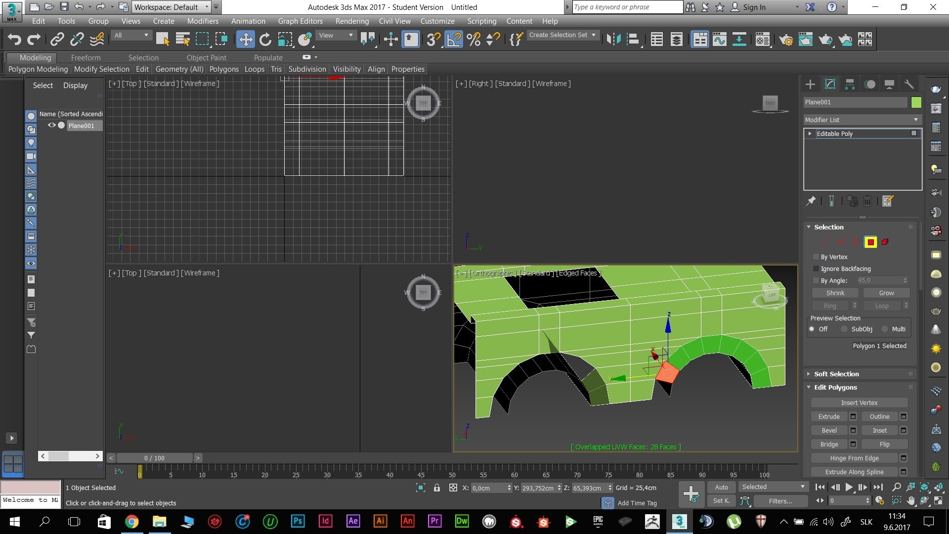


This is x-view, showing overlapping UVW faces. What is the deal here ?
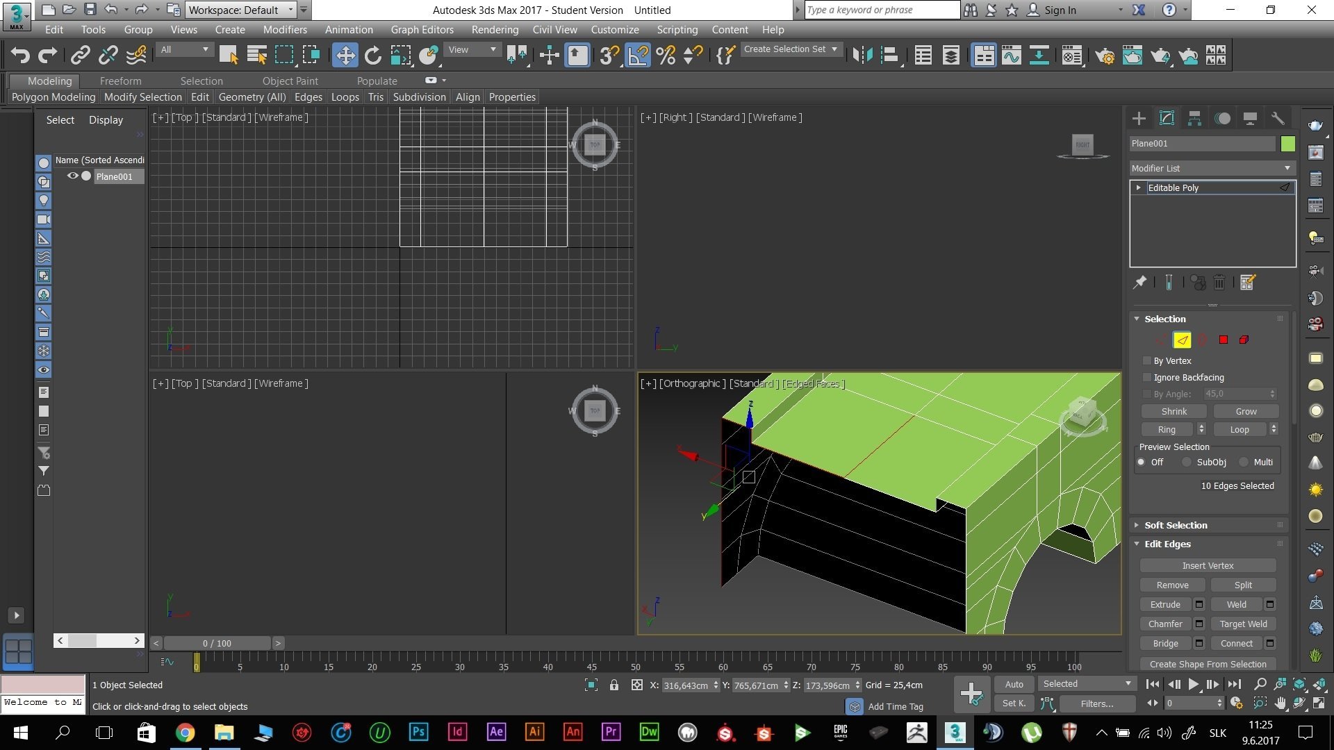


Often, I end up at point, where I am unable to select whole edge by double clicking it. Using ctrl+click does not solve the problem. Even after extruding, faces behave as two. Even if they are welded ! Now I do select whole model and vertices, welding all of them with 0,01 tolerance.  Therefore there shouldn't be any issues. But as you can see, there are.

Now that leads to double edges issue. If I weld vertices after each extrusion, how do double faces happen to be there ? Also, double faces are only visible using x - view. Its pretty much not possible to tell them apart and delete the right ones.

And finally, what is the impact of this on games engines or rendering ? As long as faces are not overlapping everything should be fine, shouldn't it ?

Replies

  • musashidan
    Offline / Send Message
    musashidan high dynamic range
    You should start by doing some VERY basic modeling tutorials/excercises, to understand how 3d modeling works. If you understand the concepts of how verts/edges/faces relate to one another and how they behave on a polygonal surface then you can avoid these topology issues. You can't just weld verts if they are not connected by edges. This is what collapse does but that is destructive unless you know when/why to use it.

    The reason xview is showing overlapping uvw is because your mesh hasn't been unwrapped yet. You can see this for yourself if you add an unwrap uvw modifier. The uvs will be a jumbled mess.

    Do some very basic modeling excercises on a plane or a box to get used to what the tools do.


  • Filip5
    Offline / Send Message
    Filip5 polycounter lvl 9
    @musashidan

    I understand that 2 vertices create edge, 4 edges create face. And and everything should be 4 - quads if possible. And I understand smoothing.  If you weld vertices, they become one. (theoretically if you weld face, you get edge, although it doesn't work that way) . I also know that extrusion creates new vertices at same position, but duplicates them. However, welding should do the trick.
    I also know about retypology, how to affect smoothing, smoothing groups...

    What exactly should I try or what should I watch ? 


  • Filip5
    Offline / Send Message
    Filip5 polycounter lvl 9
    Alright, I did a quick video on this. This is the process I use, and I  run into overlapping faces  this time, but also strange loops. I could delete the overlapping parts but I need to learn how not to create them... I have noticed there was something wrong at 2:00 minutes, although I don't get it.

    https://streamable.com/hu38t
  • musashidan
    Offline / Send Message
    musashidan high dynamic range
    The problem is that you're using the extrude edge tool with zero width/height. This means there are 3 edges sitting on top of eachother after the operation. The original edge and the 2 extruded edges. And because the edges are all co-planar they can be hidden by the shading depending on where they are moved. This is also why weld doesn't do what you think it might because, as I mentioned above, you can't weld verts that are not connected by an edge. You would have to collapse the verts/edges.

    You should be using shift+drag to create new edges for this purpose. As I also said above, this is a case of learning the basic functions of the tools.
  • musashidan
    Offline / Send Message
    musashidan high dynamic range
    @perna I'm not sure mate as I've never had the need to do it. :)

    As for OP, I think you must be coming from another modeling package, as peran observed,  where extrude edge behaves as you were expecting.
  • Filip5
    Offline / Send Message
    Filip5 polycounter lvl 9
    Actually, I never heard anything on youtube mentioning shift + drag. All the people used 0 and 0 for extrusion. True, they didn't use x-view. I ll give it a go. Thank you guys.
  • musashidan
    Offline / Send Message
    musashidan high dynamic range
    @perna sadly, I don't even think the newer generations even know about the docs. I still flick through my old Max docs, over a cup of tea, from back in the day when paper was popular. I still have some of those Max Bible volumes from r4/r5 from when I was starting out. :)

    OP - as per perna's advice, here's a copy/paste from the mysterious and archaic Max official documentation:

    Cloning Sub-Object Geometry

    Using Shift+transform with a selection of vertices or faces displays the Clone Part Of Mesh dialog. This lets you choose whether to clone to a separate object or an element. Click the desired option, optionally giving the cloned object a new name, then click OK.

    • If you choose Clone To Object, the cloned copy becomes a plain mesh object, entirely separate from the original object. The new object is given the name in the field to the right of the Clone To Object radio button.
    • If you choose Clone To Element, the selection is cloned in its new position and remains part of the original object.


    Now this doesn't specifically mention edge extrusion but 3d modelling is all about experimentation. If you had known about cloning sub-objects you would surely have discovered the edge extrusion function. This is also an important technique when used with border sub-object move/scale/rotate.
  • Filip5
    Offline / Send Message
    Filip5 polycounter lvl 9
    I appreciate the help and support from you guys, although I need to say that I am freshly graduated digital artist. I take 3D as my hobby, never took it professionally at school. There are tons and tons of functions I haven't discovered  in Max yet.  Therefore, I try to discover and solve things which I come across. You are right about documentation, but since I don't use Max on daily basis, it is far more efficient for me to ask here, on polycount. Experienced users like you can often explain better and shorter.
  • Filip5
    Offline / Send Message
    Filip5 polycounter lvl 9
    Guys I didn't want to make separate thread for this. What is the deal with t - vertices ? Are they like to have them with lower polycount or not to have them adding a lot of faces ? 


    What about parts that were closed with cap modifier ? Should I just use cut tool to connect remaining vertices ? ( I did search even Max documentation online this time, just no mention of t - vertices)

  • Filip5
    Offline / Send Message
    Filip5 polycounter lvl 9
    perna said:
    Don't use cut, use connect. Or simply move the vertex so you get a clean ngon.
    Alright, but what about those t - vertices ?
  • musashidan
    Offline / Send Message
    musashidan high dynamic range
    Xview implementation or 'warning' about T-verts is to be ignored. Simple test: create a box>enable XV T-Verts>8 verts detected....

    In your image with the highlighted red edgeloop, it terminates and results in a triangular quad. What exactly are you asking us? And what is it you're intending to do with that edgeloop?
  • Filip5
    Offline / Send Message
    Filip5 polycounter lvl 9
    I was just interested about t - vertices, how they affect final model. I didn't intend to add that loop there. The original question was whether to prefer less t - vertices and much more faces or t - vertices are fine and can be used whatsoever. 
  • musashidan
    Offline / Send Message
    musashidan high dynamic range
    With modeling it comes down to how good the model looks when shaded. Whether it's polygonal surface shading or sub-division smoothing. There are rules and guidelines and best practices. None are necessarily hard and fast. They can be bent. Everyone has their own way of modeling and getting to the end result as quickly and efficiently as possible. It takes a LOT of study, and more importantly, practice. Hours and hours of modeling. Not that that's bad because if you're going to be doing it and getting good at it you need to enjoy doing it.

    Knowing the terminology is one thing. The important thing is putting it to use. There's no answer to the last question you asked. You as the modeler need to judge this yourself. If it looks good, it is good. Learn about topology.  Understanding that is the foundation.
  • kanga
    Offline / Send Message
    kanga quad damage
    I always run an xview check on my models. I've been doing this for a while, and although the modelling mistakes decrease, there are still a few. I noticed everything you do in a 3d program has consequences. You cant wildly click about the viewport without consequence. Your having these modelling problems because you haven't been doing it long. Even when you have, checking your work is always a good practice.
Sign In or Register to comment.