How to split and cap a model for 3D printing

Hi guys,
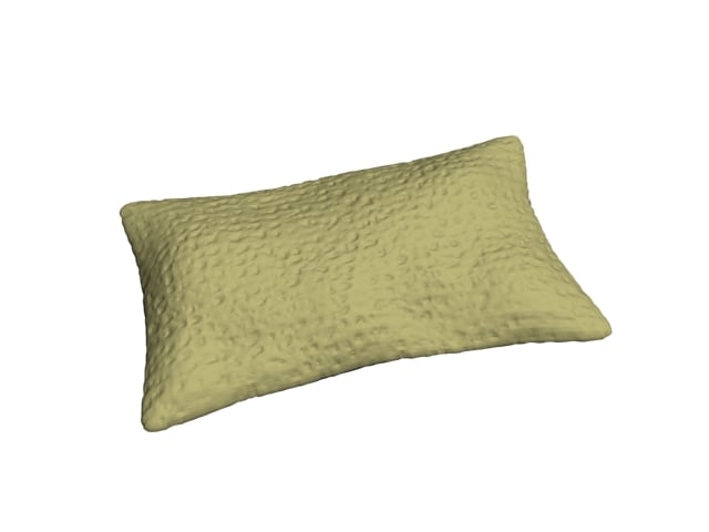
This is my first post on the forum, and I need a bit of advice from you guys. I've got a particular 3D model built using 3ds Max that I am trying to format for 3D printing. It's a humble sandbag, with displacement-mapped burlap texture, intended for use with 1:18 scale military figures (like G.I. Joe).
It passes an STL check just fine. However, in order for the model to print well, the model needs to have a flat-bottomed surface to adhere to the build-tac on the print bed. So what I need to do is split the model in half along its midsection (X/Y axis), and cap both of the halves so each has a flat surface for printing. The two halves can then be glued together to make the finished model. However, I am having a difficult time getting the split and cap to work as I need. I can split the mesh fairly easily (either using the Slice modifier, or by using a Boolean), but when I attempt to add a Cap Holes modifier, I wind up with what could best be described as a sort of Shell effect.
For more information, here's a basic rundown of how the model is created:
*I start with a basic Plane, with enough subdivisions to create a convincingly lumpy shape. (Note that I'm using a pretty old [educational] version of Max.)

*Then, I add a Turbosmooth to create more subdivisions.

*Afterwards, I apply a Cap Holes to give it a nice, flat bottom. (Note that this modifier doesn't seem to influence the final result, but I add it anyways.)

*Then, I apply Symmetry. The edges are welded.

*Next, I apply a Displacement Approx and a Displace Mesh Binding effect. (I found that stacking the two really makes the displacement mesh "pop" a lot more than just using one or the other, though I can get similar results with just Displace Mesh Binding.) This results in the image at the top.

*Lastly, I create a Snapshot of the model to bake in the stack. This is the version I'm attempting to split in half.
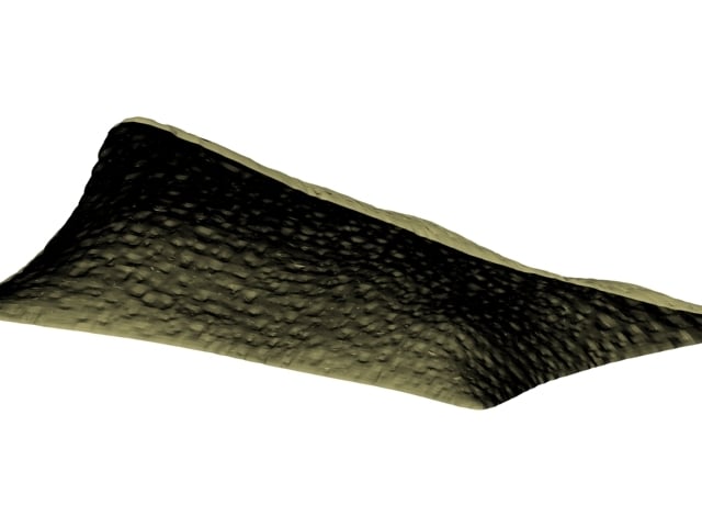
Oh, and if I skip the Symmetry modifier, but apply all the others, this is the result I get--lots of holes. (In fairness, I probably don't want the displacement map applied to the bottom of the mesh, but I'm not exactly sure how to apply a displacement map to only a certain portion of a model and not others.)
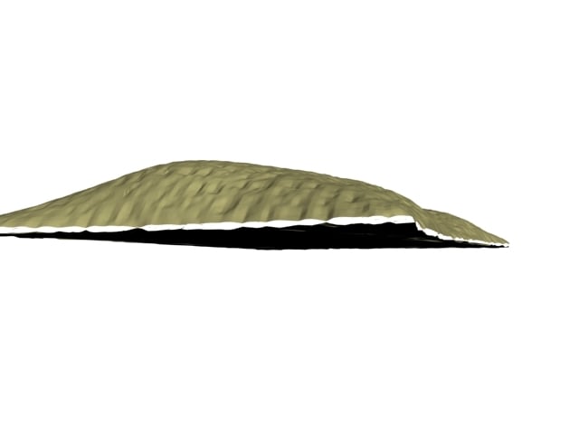
*EDIT: I realized that I should turn "Split Mesh" off. This gets rid of the holes, though the bottom surface is still not quite flat.
So, does anybody have any recommendations on how to cleanly split the mesh down the middle so that both halves have a smooth cap? Is there a difference in the workflow I should be using that will produce better results? Is there a 3rd-party utility that can do the trick? Anyways, this is a conundrum I really need to get worked out, since I have a number of other models that will eventually need to be split in a similar fashion in order to ensure a smooth print job.
Thanks in advance! I appreciate any constructive feedback or advice.
This is my first post on the forum, and I need a bit of advice from you guys. I've got a particular 3D model built using 3ds Max that I am trying to format for 3D printing. It's a humble sandbag, with displacement-mapped burlap texture, intended for use with 1:18 scale military figures (like G.I. Joe).
It passes an STL check just fine. However, in order for the model to print well, the model needs to have a flat-bottomed surface to adhere to the build-tac on the print bed. So what I need to do is split the model in half along its midsection (X/Y axis), and cap both of the halves so each has a flat surface for printing. The two halves can then be glued together to make the finished model. However, I am having a difficult time getting the split and cap to work as I need. I can split the mesh fairly easily (either using the Slice modifier, or by using a Boolean), but when I attempt to add a Cap Holes modifier, I wind up with what could best be described as a sort of Shell effect.
For more information, here's a basic rundown of how the model is created:
*I start with a basic Plane, with enough subdivisions to create a convincingly lumpy shape. (Note that I'm using a pretty old [educational] version of Max.)
*Then, I add a Turbosmooth to create more subdivisions.
*Afterwards, I apply a Cap Holes to give it a nice, flat bottom. (Note that this modifier doesn't seem to influence the final result, but I add it anyways.)
*Then, I apply Symmetry. The edges are welded.
*Next, I apply a Displacement Approx and a Displace Mesh Binding effect. (I found that stacking the two really makes the displacement mesh "pop" a lot more than just using one or the other, though I can get similar results with just Displace Mesh Binding.) This results in the image at the top.
*Lastly, I create a Snapshot of the model to bake in the stack. This is the version I'm attempting to split in half.
Oh, and if I skip the Symmetry modifier, but apply all the others, this is the result I get--lots of holes. (In fairness, I probably don't want the displacement map applied to the bottom of the mesh, but I'm not exactly sure how to apply a displacement map to only a certain portion of a model and not others.)
*EDIT: I realized that I should turn "Split Mesh" off. This gets rid of the holes, though the bottom surface is still not quite flat.
So, does anybody have any recommendations on how to cleanly split the mesh down the middle so that both halves have a smooth cap? Is there a difference in the workflow I should be using that will produce better results? Is there a 3rd-party utility that can do the trick? Anyways, this is a conundrum I really need to get worked out, since I have a number of other models that will eventually need to be split in a similar fashion in order to ensure a smooth print job.
Thanks in advance! I appreciate any constructive feedback or advice.
Replies
Does the printer in question not utilise support structures? These are temporary 'scaffolding' that you can use to stabilise and support the model,and then you just remove them and sand the area post print.
The printer I have does offer support structures (including "rafts"), but I want to try to avoid them in this case since loss of detail is inevitable. I will also have a few other models that will need to be split in similar manner for structural reasons, such as this jersey barrier:
Which, once split in half, I'll want to hollow out each half (presumably using "Shell") in order to reduce the amount of plastic needed to create it. (Note that this will also be displacement mapped eventually, so pretty much the same problem will apply.)
Also, as a side note, if I Slice the mesh before having applied any displacement map, then use Cap Holes, it does exactly what I would expect--it creates a smooth surface on the bottom. The problem seems to be with applying Cap Holes AFTER the mesh has had a displacement applied. Any ideas why that might be the case?
Method 1 - slice the mesh>apply displace mod>apply cap holes(or you could apply edit poly mod>border select>cap)
Method 2 - slice the mesh(use a slice mod to maintain the stack>apply edit poly mod>cap the border>select the new capped geo>invert it>now send this selection up the stack to the displace mod to only displace the selected geo below in the stack(this can also be done with a mesh select mod or a volume select mod)
Edit: just realised you're using the displace approx mod. Just use the displace mod, apply your disp map, snapshot to mesh.
Method 1 -- If I slice the mesh, then apply the Displace mod, then apply Cap Holes, I get lots of holes around the cap area, even with "Split Mesh" off. I tried using the Edit Poly Mod > Border Select > Cap method, and that didn't work either, unfortunately. It appears to have simply generated a duplicate set of inverted polygons around the lower border rather than capping the entire "hole". (I think it believes the "hole" is just the bottom-most row of polygons.)
Method 2 -- How would I send the selection "up the stack"? I'm not sure I know how to do this. Or maybe I do, but I don't know it by that term.
Like I said, I can easily cap the hole as long as the mesh hasn't had a Displace modifier applied yet. I don't know why Displace is causing so many problems. Let me tell you, this is driving me batty!
EDIT: If you're interested, I can post a copy of the 3ds scene here for you to play around with. Maybe your (presumably newer) version of Max will handle it better.
No problem, post the scene and I'll take a look.
Sending a selection up the stack just means adding a modifier whilst a sub-object selection is active. This means that the mod on top of the modifier stack will only affect the selection from below. So if you select verts/faces/etc and apply the displace mod, only the selected faces will be affected by the displace effect.
https://www.dropbox.com/s/iimwwx1smqshys4/sandbag.max?dl=0
"Sandbag" is the object created from the stack, with all the stack effects active. "Sandbag01" is the snapshot version (with the pivot centered to the object). There's also a "collapsed and resized sandbag", which is the same snapshot version at 1/18 scale.
Also, here's a link to the displacement map image in case you need it.
https://www.dropbox.com/s/5nd7rmlewm8ad3e/sandbag displacement map copy.png?dl=0
Anyways, I really appreciate your help so far! This displacement map stuff is really promising for adding textured details to models I want to 3D print (since I'm not versed in traditional sculpting methods) but is definitely a bit tricky to get a handle on.
Your snap-shotted mesh is completely broken, The topology is a mess and all the verts are unwelded. I would also advise working with editable poly geometry rather than editable meshes.
The simplest way to do this is:
Take your original mesh>apply the DISPLACE modifier(after a few turbosmooths)>put your map in the map slot>snapshot to mesh>slice modifier(split mesh radio button checked and gizmo aligned>edit poly mod(or collapse to editable poly)>select both open borders created by the slice mod>cap(from edit borders rollout in the command panel)>now you have 2 perfectly aligned halves with perfectly flat bottoms.