3ds Max - Substance Painter - Marmoset Toolbag normal map on metal surface

vertex
Hello everybody, this is my first post here ")
I've encountered a problem with my candelabrum model, so I simplified the process to narrow it down and as it turns out it persists on a cube. Long story short, it looks OK in Substance Painter but not so OK in Marmoset Toolbag 2. I'm talking about those black artifacts on the edges.
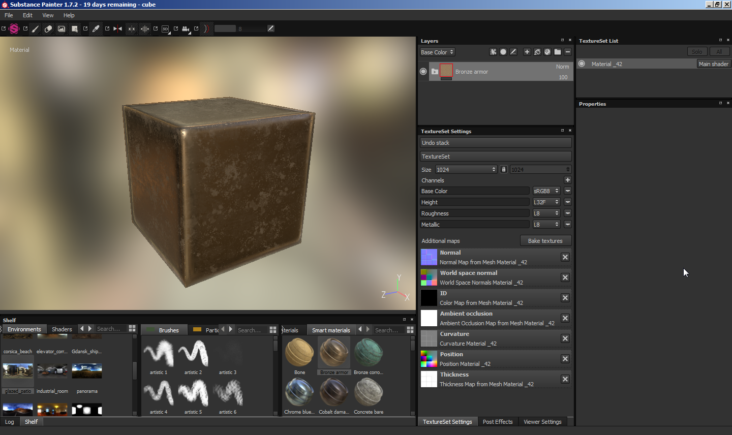
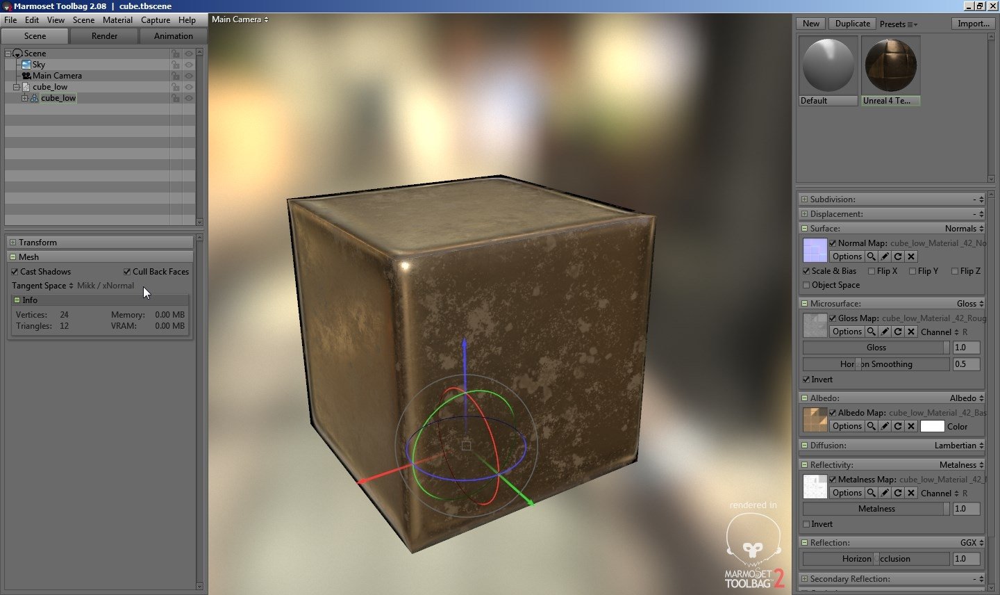
With just the normal map it looks more or less the same in both programs, but problems appear as soon as I switch reflectivity mode to metalness, without even plugging in any extra maps.

The low poly cube is the simplest 8 verts version with all hard edges and 6 UV islands. I exported an FBX from 3ds Max without tangents and binormals so that they're supposed to be computed in the Mikkt space in SP, and in Marmoset the mesh is also set to Mikkt.

Any suggestions?
I've encountered a problem with my candelabrum model, so I simplified the process to narrow it down and as it turns out it persists on a cube. Long story short, it looks OK in Substance Painter but not so OK in Marmoset Toolbag 2. I'm talking about those black artifacts on the edges.
With just the normal map it looks more or less the same in both programs, but problems appear as soon as I switch reflectivity mode to metalness, without even plugging in any extra maps.
The low poly cube is the simplest 8 verts version with all hard edges and 6 UV islands. I exported an FBX from 3ds Max without tangents and binormals so that they're supposed to be computed in the Mikkt space in SP, and in Marmoset the mesh is also set to Mikkt.
Any suggestions?
Replies
Edit2: checked on the candelabrum model, with Blinn-Phong it's much more acceptable, although there's one element that had no artifacts with GGX and looks a bit less photorealistic with Blinn-Phong. It's also the only element on which I used one smoothing group (no hard edges).
Candelabrum has 2391 verts, 4802 tris, as shown in 3ds Max. I wanted to solve the problem on a cube before asking you nicely for feedback on the candelabrum itself.
http://polycount.com/discussion/81154/understanding-averaged-normals-and-ray-projection-who-put-waviness-in-my-normal-map/p1
I think the metallic material is just making those black bits more obvious, I don't think it's really related to the cause. Try seeing what happens if you add some supporting loops.
It could also be a mip mapping thing? Have you got padding on your normal maps? If not try that first.
If you look at one of the images I included in my first post, you can see my UVs. I have padding, and I used averaged normals in Substance Painter. When I baked in Max as a test, I used the default settings (except pushing the cage out), meaning averaged normals too.
I don't want to add supporting loops if I don't have to. I spent hours reading the wiki and the stickied threads (and most of the replies) for a few days, it was a lot of knowledge in a short time, maybe too much, so I may have confused some things in the end, but from what I understand if you do things right with smoothing groups, UVs, proper baking and synced workflow, you should be alright without supporting loops.
R1 is the reflection vector that you get from the cube if it's not normal mapped and has hard edges there. R2 is the reflection vector that you would get from the highpoly cube. These vectors or something similar are used to look up the color of the reflection in a cubemap. At the edge of the cube, the normal map is giving a reflection vector around R2, which is off by a lot from R1. Also, at the edge of the cube there are a few pixels that the lowpoly encompasses that the highpoly doesn't. It all amounts to a situation where it's impossible to get an accurate reflection in that spot. In a pathtracing render engine like Cycles, Arnold, or RIS this problem is usually a lot worse.
You probably didn't notice this on a dielectric surface because there's diffuse there, which doesn't have this problem to the same extent.
So, basically what needs to happen here is that your lowpoly needs to match the highpoly better. Usually you'll want to do this by adding more geometry. If you start getting to the point with your added geometry where you're getting triangles that are less than 1 or 2 pixels wide that's when you'd want to make another LOD that has around the same vertex count as your original geometry (actually for optimal performance you should aim for mostly triangles that are around 3-4 pixels across minimum, but below 1 is where you really start to feel the burn.) Here's how the bake looks with a path traced cube that's been beveled with 2 divisions for a total of 56 verts. You can still see some black on the left and bottom left edges but it's much less pronounced.
I picked a path tracer because problems like this are usually more pronounced in a path tracer. You probably wouldn't notice any sort of problem in a real-time renderer with a mesh that's this close to the highpoly.