Best projection mapping workflow?
Hello,
I've always had a big problem with trying to project high sculpted detail onto a low resolution mesh, maybe because I am missing a crucial step. I wondered if anyone could give some tips or a suggested workflow for getting the best results possible.
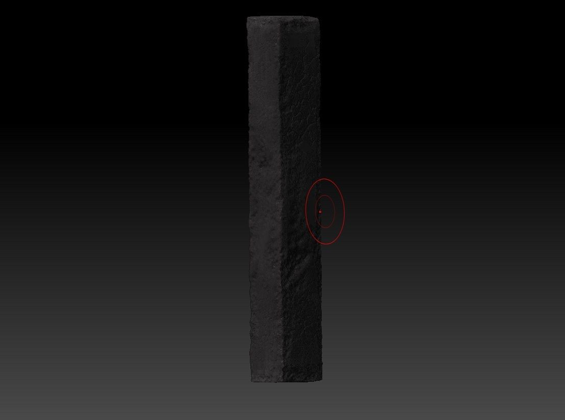
I will lay out an example here (Simple broken concrete pillar):
1). So I started out with a low poly base with sharp edges so they wouldn't smooth out in zbrush. Also UV mapped because I planned on polypainting this as a test.

2). Imported the model into zbrush and sculpted some basic wear and tear for the look of the concrete.
3). I slightly decimated the pillar from zbrush and merged it into the max scene with the low initial mesh.
4). I put the two objects inside one another, at 0,0,0.
5). Press "0" on the keyboard to bring up the projection mapping options. Picking the high poly mesh as a projection. Choose existing channels. Add a normals map of about 1024x1024. Then proceeding to the modifier panel and adjusting the cage to fit around both objects.
6). Then choosing to render the normal map.
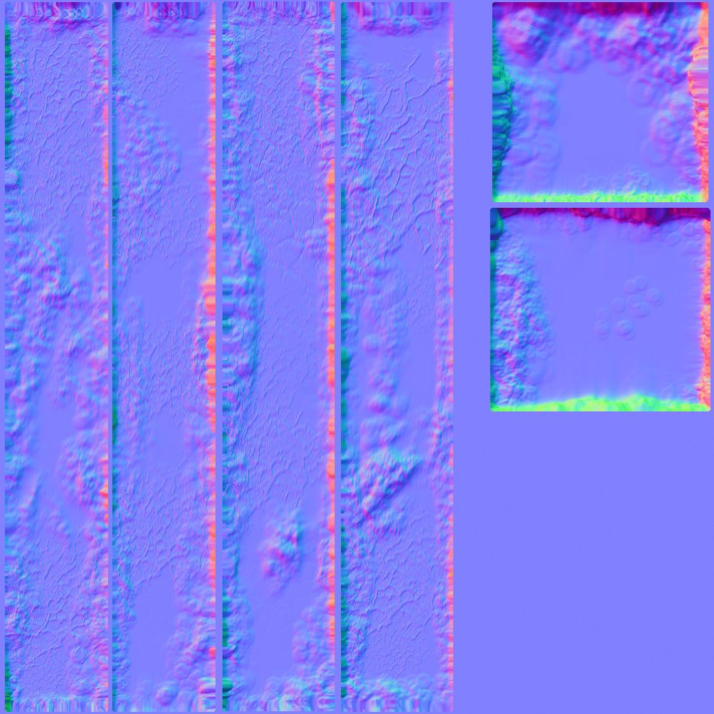
I think my major issue here, is the red areas of error maybe due to the original mesh not being big enough? Although does it seem that this normal map needs inverting?
So... That is the process I normally go through, yet I don't seem to get a very good normal map. Is it a case that I need to add more edges to the centre of the low poly object and/or retop the entire mesh? I only stayed away from retopping is about the mesh isn't changed to such I degree that I thought it would need it so.
Thanks for any help!
I've always had a big problem with trying to project high sculpted detail onto a low resolution mesh, maybe because I am missing a crucial step. I wondered if anyone could give some tips or a suggested workflow for getting the best results possible.
I will lay out an example here (Simple broken concrete pillar):
1). So I started out with a low poly base with sharp edges so they wouldn't smooth out in zbrush. Also UV mapped because I planned on polypainting this as a test.
2). Imported the model into zbrush and sculpted some basic wear and tear for the look of the concrete.
3). I slightly decimated the pillar from zbrush and merged it into the max scene with the low initial mesh.
4). I put the two objects inside one another, at 0,0,0.
5). Press "0" on the keyboard to bring up the projection mapping options. Picking the high poly mesh as a projection. Choose existing channels. Add a normals map of about 1024x1024. Then proceeding to the modifier panel and adjusting the cage to fit around both objects.
6). Then choosing to render the normal map.
I think my major issue here, is the red areas of error maybe due to the original mesh not being big enough? Although does it seem that this normal map needs inverting?
So... That is the process I normally go through, yet I don't seem to get a very good normal map. Is it a case that I need to add more edges to the centre of the low poly object and/or retop the entire mesh? I only stayed away from retopping is about the mesh isn't changed to such I degree that I thought it would need it so.
Thanks for any help!
Replies
Also, harden all UV shell border edges.
Next, harden the UV shells (Textools and Turbotools both have this function) to Smoothing Groups. UV islands = SG, also make sure you support loops are reading correctly.
Next, make sure you're selecting the proper channels in the baker, etc.
As for if the model is big enough, generally this isn't an issue if the model can be seen in the grid well enough and you have resented your XForm,
In addition to that you've got pixel padding which stretches the pixels out(to help with mip mapping) this looks weird but is in no way a bad thing.
So yeah, what does it actually look like in 3d, impossible to "debug" a normal map by looking at the 2d image.