Documentation: Easy Perspective Lines & Grids for Unreal Engine
polycounter lvl 6
Available on Fab and Gumroad
Contents:
1. Introduction
2. Perspective Lines
2.1. Setup
2.2. Settings & Features
2.2.1. Default
2.2.2. Tags
2.2.3. Toggle Line Types
2.2.4. Line Dimensions
2.2.4. Material Settings
3. Perspective Grid
3.1. Setup
3.2. Settings & Features
3.2.1. General Settings
3.2.2. Toggle Lines
3.2.3. Line Dimensions
3.2.4. Material Settings
Under the menu "Default", you have a checkbox called "Recalculate Perspective Lines". Click this box to update your perspective lines, once you made changes to the scene. This box acts as a button, and will reset to false each time you click it.
2.2.2. Tags
You have the option to decide whether tags should be used to define where perspective lines are generated, or if they should be generated for every object in the scene. Toggle this, with the setting "Use Tags".
When "Use Tags" is enabled you need to apply tags to each actor you want perspective line to be generated at. You can define what these tags are, by changing the "Tag Name". Change the Tag Names when you have multiple BP_PerspectiveLines blueprints, with different settings, in your level.
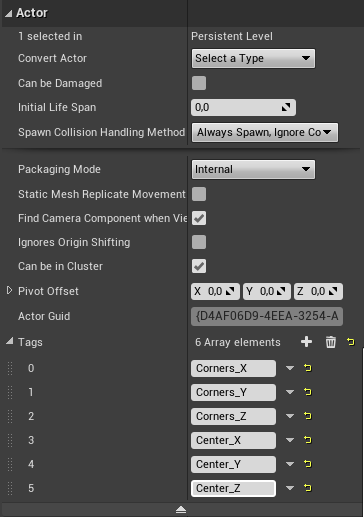
To apply tags to an object, first select the object, then in the details panel go to the menu "Actor" > "Show Advanced". Click the + icon next to "Tags", and type in the tag name defined in the blueprint. Add additional Tags for each type of lines you want to be generated for that object.
Check out the level "L_PerspectiveLines_Overview" under "Content" > "PerspectiveLinesAndGrids" > "Levels", to see how the tags are applied there.
2.2.3. Toggle Line Types
These settings are only relevant when "Use Tags" is unchecked. In this case, perspective lines are generated along every object in the level, but you first have to select what type of lines are created. Check the boxes one by one and the lines will start appearing.
2.2.4. Line Dimensions
"Line Length" sets the length of all lines created by the blueprint. Value 1,0 means the lines have the exact length of the objects they are generated at. The value multiplies that length, so value 3,0 means the lines will be 3x the length of the object.
If you want the different line types to have different lengths, you need to add multiple BP_PerspectiveLines blueprints to the level. Check the levels "L_PerspectiveLines_Overview" and "L_PerspectiveLines_Example", to see how this is done with and without tags.
The "Line Thickness" can be adjusted for each line type separately.
2.2.5. Material Settings
For each line type, you can adjust the "Base Color", "Emissive Color", "Metallic" and "Roughness" values separately.
Go to "Content" > "PerspectiveLinesAndGrids" > "Blueprints" and drag & drop "BP_PerspectiveGrid" into your level. A basic X/Y grid will appear at the center of the level. You can change the look and size of it later on.
"Lock Grid To 0,0,0": This setting causes that the grid will always be positioned at the center of the level, disregarding the position of the blueprint. By default, this is enabled. Disable the option, and you can position the grid freely, by moving the blueprint.
"Grid Extent": How many subdivisions the grid has. Multiplied by "Grid Spacing (cm)", it determines the overall size of the grid.
"Grid Spacing (cm)": The size of each subdivision in centimeters.
"Major Lines Every Nth Grid Line": Defines after how many subdivisions a thicker line will appear.
3.2.2. Toggle Lines
The 2D Grid consists "Center Line", "Grid lines" and "Major Grid Lines". They can be toggled seperately for all 3 axes. By default, only the floor grid (X, Y) is enabled.
Volumetric Lines expand the grid to 3D space. They are generated with the same spacing as the Grid Lines and Major Grid Lines. They can, for example, be used as a simplified version of the perspective lines.
3.2.3. Line Dimensions
The thickness of the lines can be adjusted for each line type separately.
"Volumetric Lines - Length Multiplier" changes the length of the volumetric lines. By default, they have the same length as the grid itself. This value multiplies this length, so a value of 2 means, they are double the length of the grid.
3.2.4. Material Settings
The "Metallic", "Roughness", "Base Color" and "Emissive Color" values can be set for each line type separately.

Contents:
1. Introduction
2. Perspective Lines
2.1. Setup
2.2. Settings & Features
2.2.1. Default
2.2.2. Tags
2.2.3. Toggle Line Types
2.2.4. Line Dimensions
2.2.4. Material Settings
3. Perspective Grid
3.1. Setup
3.2. Settings & Features
3.2.1. General Settings
3.2.2. Toggle Lines
3.2.3. Line Dimensions
3.2.4. Material Settings
1. Introduction
"Easy Perspective Lines & Grids" is a blueprint tool for Unreal Engine, which enables you to quickly create perspective lines in your scene, or spawn a perspective grid, which supplements the default engine grid with several advanced functionalities.2. Perspective Lines
2.1. Setup
Go to "Content" > "PerspectiveLinesAndGrids" > "Blueprints" and drag & drop "BP_PerspectiveLines into your level. Once you have placed the blueprint, lines along the X axis will appear for all object. You can adjust that and define where which type of lines will be generated. How to do that will be subject of section "2.2.2. Tags" and "2.2.3. Toggle Line Types".2.2. Settings & Features
2.2.1. DefaultUnder the menu "Default", you have a checkbox called "Recalculate Perspective Lines". Click this box to update your perspective lines, once you made changes to the scene. This box acts as a button, and will reset to false each time you click it.
2.2.2. Tags
You have the option to decide whether tags should be used to define where perspective lines are generated, or if they should be generated for every object in the scene. Toggle this, with the setting "Use Tags".
When "Use Tags" is enabled you need to apply tags to each actor you want perspective line to be generated at. You can define what these tags are, by changing the "Tag Name". Change the Tag Names when you have multiple BP_PerspectiveLines blueprints, with different settings, in your level.
To apply tags to an object, first select the object, then in the details panel go to the menu "Actor" > "Show Advanced". Click the + icon next to "Tags", and type in the tag name defined in the blueprint. Add additional Tags for each type of lines you want to be generated for that object.
Tip: You can select multiple object at once to apply tags to all of them.
Check out the level "L_PerspectiveLines_Overview" under "Content" > "PerspectiveLinesAndGrids" > "Levels", to see how the tags are applied there.
2.2.3. Toggle Line Types
These settings are only relevant when "Use Tags" is unchecked. In this case, perspective lines are generated along every object in the level, but you first have to select what type of lines are created. Check the boxes one by one and the lines will start appearing.
2.2.4. Line Dimensions
"Line Length" sets the length of all lines created by the blueprint. Value 1,0 means the lines have the exact length of the objects they are generated at. The value multiplies that length, so value 3,0 means the lines will be 3x the length of the object.
If you want the different line types to have different lengths, you need to add multiple BP_PerspectiveLines blueprints to the level. Check the levels "L_PerspectiveLines_Overview" and "L_PerspectiveLines_Example", to see how this is done with and without tags.
The "Line Thickness" can be adjusted for each line type separately.
2.2.5. Material Settings
For each line type, you can adjust the "Base Color", "Emissive Color", "Metallic" and "Roughness" values separately.
3. Perspective Grid
3.1. Setup
Go to "Content" > "PerspectiveLinesAndGrids" > "Blueprints" and drag & drop "BP_PerspectiveGrid" into your level. A basic X/Y grid will appear at the center of the level. You can change the look and size of it later on.3.2. Settings & Features
3.2.1. General Settings"Lock Grid To 0,0,0": This setting causes that the grid will always be positioned at the center of the level, disregarding the position of the blueprint. By default, this is enabled. Disable the option, and you can position the grid freely, by moving the blueprint.
"Grid Extent": How many subdivisions the grid has. Multiplied by "Grid Spacing (cm)", it determines the overall size of the grid.
"Grid Spacing (cm)": The size of each subdivision in centimeters.
"Major Lines Every Nth Grid Line": Defines after how many subdivisions a thicker line will appear.
3.2.2. Toggle Lines
The 2D Grid consists "Center Line", "Grid lines" and "Major Grid Lines". They can be toggled seperately for all 3 axes. By default, only the floor grid (X, Y) is enabled.
Volumetric Lines expand the grid to 3D space. They are generated with the same spacing as the Grid Lines and Major Grid Lines. They can, for example, be used as a simplified version of the perspective lines.
3.2.3. Line Dimensions
The thickness of the lines can be adjusted for each line type separately.
"Volumetric Lines - Length Multiplier" changes the length of the volumetric lines. By default, they have the same length as the grid itself. This value multiplies this length, so a value of 2 means, they are double the length of the grid.
3.2.4. Material Settings
The "Metallic", "Roughness", "Base Color" and "Emissive Color" values can be set for each line type separately.
