Understanding Cubemaps
polycounter lvl 6
I'm sure this has been asked before, but I can't seem to find anything exactly on it... In my pursuit of becoming a shader guru I am finally finding time to jump into UDK. I am just trying to understand how the simple cubemap setup works as it seems like a very commonly used method.
In the screenshot below, I believe the Vector Transform node is to tell UDK how to position the 6 images of the Cubemap to properly stitch together, but what is the Reflection Vector doing?
Thanks in advance")
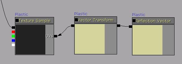
In the screenshot below, I believe the Vector Transform node is to tell UDK how to position the 6 images of the Cubemap to properly stitch together, but what is the Reflection Vector doing?
Thanks in advance
Replies
As I said its the reflection node here that is confusing me. The vector transform is essentially the cubemap compiler (I think), so what is the reflection vector doing?
Is the reflection vector saying that this whole chain is for reflections, which then plugs into the cubemap to be the reflection?
Hopefully I am making sense.
When you're learning the material editor, this page is a gold mine:
http://udn.epicgames.com/Three/MaterialsCompendium.html
Edit: Oops, mixed up world/transform coordinates!
You have 6 textures representing the insides of a cube. They exist as a single construct that you access in UDK via a cubemapsampler.
To get a color from this cube surface, you need to project a direction into it and see what is at the end. Your viewpoint into the cube always starts at the center.
Since the cubemap is a 3d construct rather than a 2d texture, you'll need 3 coordinates to pull from its UVW coordinates. Valid ranges are -1 - + 1 on each axis. This corresponds to every direction inside a unit cube.
You can use any 3 component vector for the UVW lookup, however some are more useful than others.
A reflection vector is the view direction, reflected about the surface normal. Imagine your whole object is a mirror, and your eye shoots lasers. The reflection vector is the direction of the laser beam after it hits the surface.
This is initially in tangent space. That is the coordinate space where 0,0,0 is equivalent to the pixel or vertex on the surface.
Often, this is useful enough, However for thigns like reflections you'll want to match up the vector direction into the same space as the cube map was made in or made for. This is usually world space, and occasionally camera space. That is the coordinate system of the world where the camera is always at 0,0,0.
The vector transform node accomplishes this. It takes the direction in tangent space, and transforms it into another coordinate space. That new vector is then used as the lookup into the UVW coordinates of the cube map, and it gets the color at the pixel at the location it intersects in the cube texture.
Valias: Thanks for the in depth description man
Hmm. So why not just use the object world position node and not bother with the transform? It's already in world coordinate space.
Even if you did use object world position you'll get a single 3 vector representing the centerpoint of the object. Even if you were to normalize that vector to get a valid range for a cubemap lookup, you'd get a single color. Now if you want an object that changes color based on its direction from world center, then that may be perfect, but if you want reflection type effects you need to get the direction to sample the cubemap from on a per pixel or at least per vertex basis so that the sampled colors change across the surface of the object.
For a cubemap in worldspace, like one you get from a realtime render-to-texture cube, to accurately sample it you'd want worldspace normals of an object. The way the shader pipeline is written these aren't directly passed in, as most effects require tangent space data.. or rather most effects ASSUME tangent space data as they work on a per vertex or per fragment basis, and its the most logical space to work in for that.. like when you go to the corner store you think of walking forward the whole way, rather than charting your changes in azimuth and inclination vs the center of the earth. Same sorta reference frame goes for normal mapping on deformable objects and other things.