Abstract waving cubes - World position offset - Tutorial

grand marshal polycounter
I saw this topic coming up from time to time, and today I got involved with one of them so I decided to just make a writeup about how to approach this effect using Unreal Engine:
References:
 https://www.youtube.com/watch?v=Ld_peIKWE3A
https://videohive.net/item/abstract-surface-of-moving-cubes/18266215
https://simonschreibt.de/gat/pintable/
So the result that we are looking for , is to get some cubes moving on Z axis up and down based on a noise pattern, while not distorting them, meaning that they won't change shape, but they will change their height position.
So lets start with the very basics and break down how we can achieve this:
Its all about the uvs, and how are the values distributed. Regular UV coordinates can be represented with a 2 component vectors, 2 gradients. A horizontal one, and a vertical one. Technically they could go infinite but (or the limitation of 64 bit values?? I'm not sure) you usually sample 0-1 area , or a bit more around it when you are tiling with UVs...
This is how regular 0-1 range UV coordinates are represented using a 2 component vector:
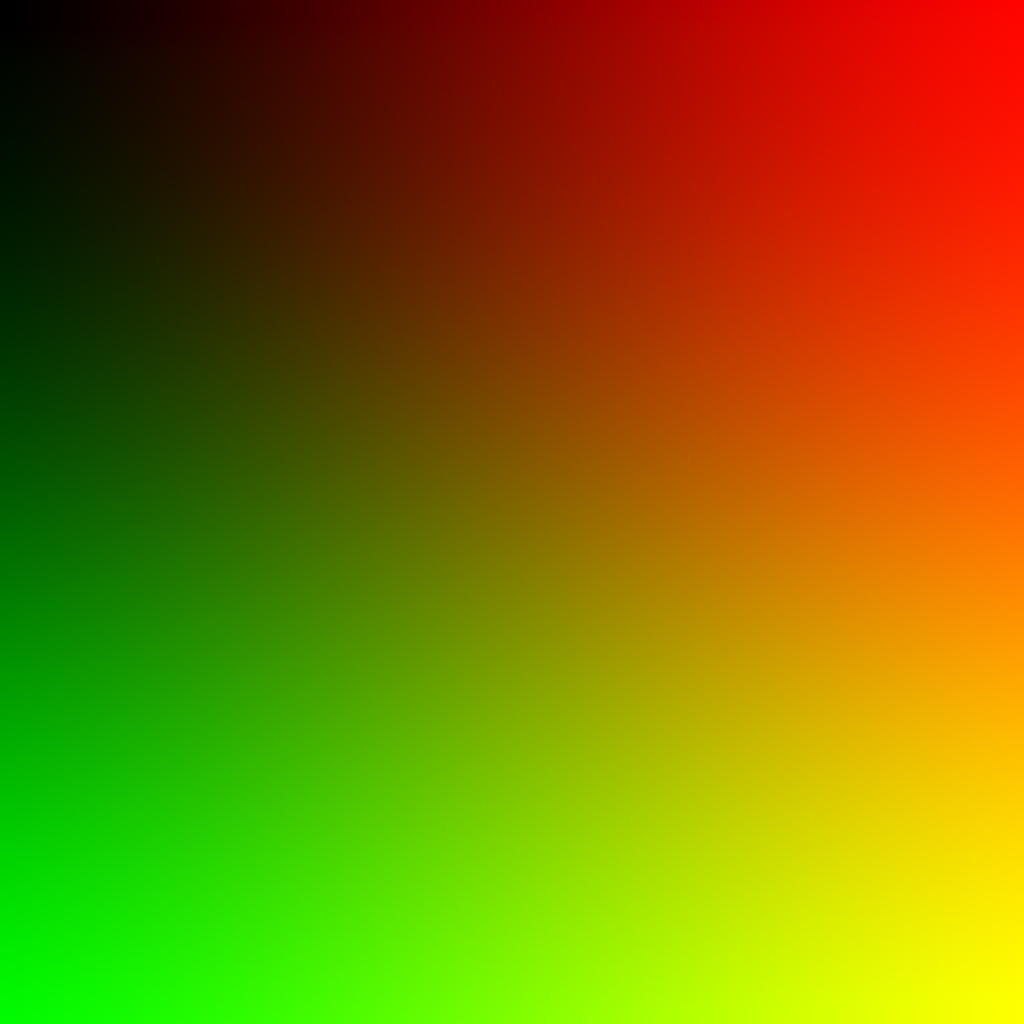
If we separate the U and the V (red and green channel), we get a horizontal and a vertical grayscale gradient. Now this is good, for continuous mapping, when you want to use the actual resolution/properties of the texture.
By adding "game time" to the coordinates, we get a panner - lets say we sample U 0 V 0 point but then on the next frame we add elapsed time or a division of that to the coordinates so the original U 0 V 0 point moves to an another location, lets say U 0.1 V 0.1, so you get a moving texture as the game updates each frame.
This is good, now we can move our noise texture that will drive the material animation. But...If we would simply pan a noise texture with these uvs, and we would take the noise values as height information, we would get the the cubes following the noise shape - distorted. So we need to do something against this.
By adding the time to a continuous value elevation, we get panning, but if we add time to "stepped" values like this, we only get value change, but not position change, and they remain stepped, rounded values:
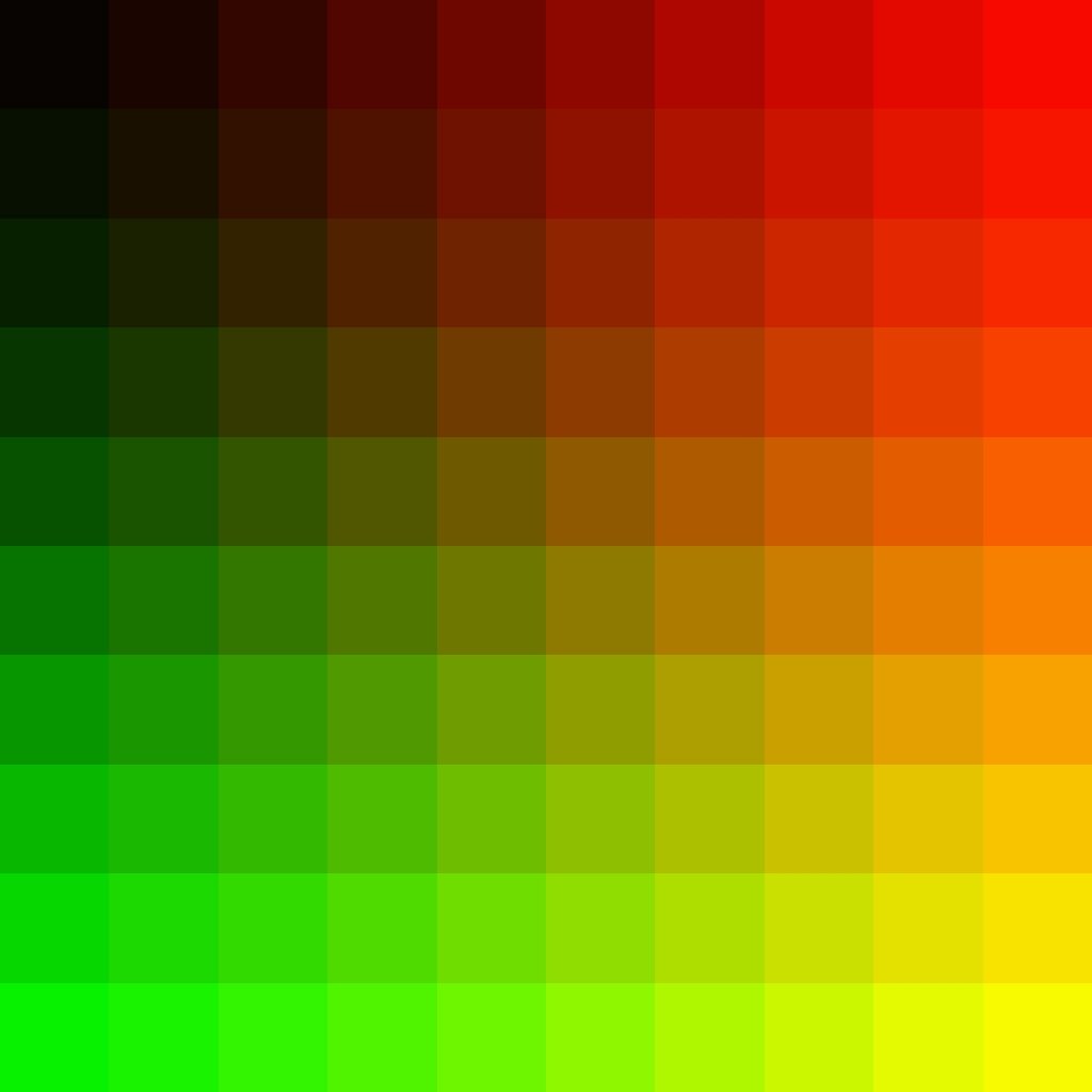
This is much more ideal for what we want, since we divided the UV map into as much "sections" as we want, as much cubes we use - In this example its 10x10
To get this effect we need to do some simple things with the coordinates:
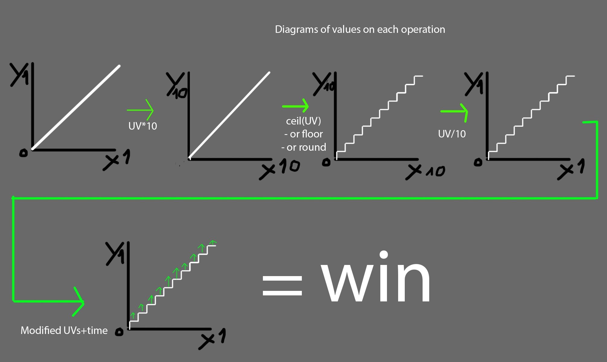
Then as its shown on the last image, when we add time, now we are good and we got the result that we need.
To set this up you need to do this:
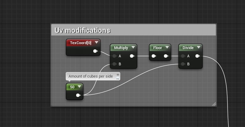
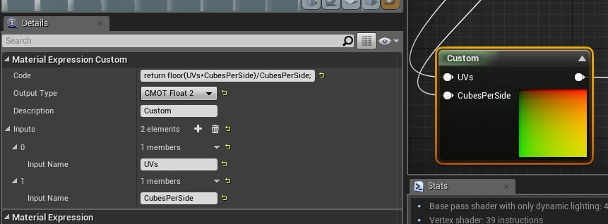
Or if you are using the "custom node" then you can use this code:
return floor(UVs*CubesPerSide)/CubesPerSide;
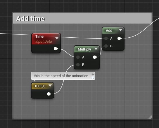
To add the game time part, do this:
Unfortunately I don't know the hlsl equivalent of time so no code example here...
....
Then this UV setup goes into the UVs of a noise texture..
And this is how our noise textrue should look, when we apply the final uvs:

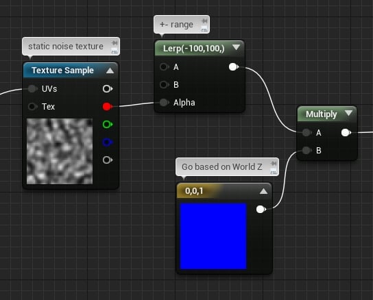
Then we use the noise texture, to lerp between min and max position values, and also we multiply it by 0,0,1 that is the world direction, so it will animate on that axis:
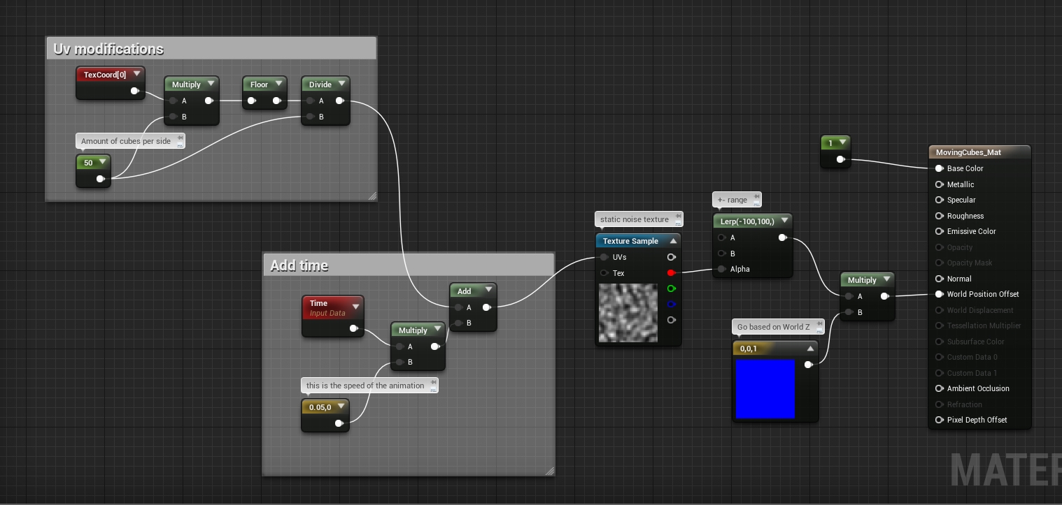
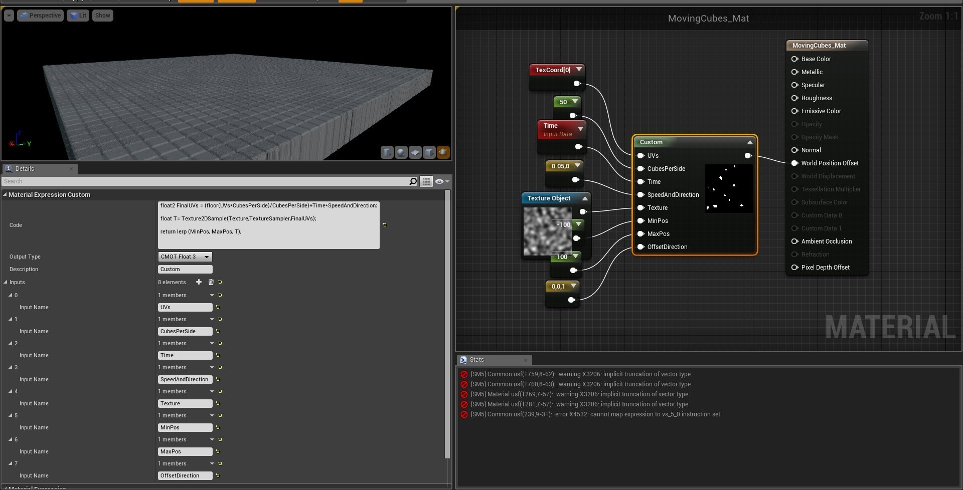
At this point, the animation is done, and the full material looks like this:
And the full code, but unfortunately you can't use texture inside the custom expression, on the vertex shader But the code would work on almost any other attribute.
I'm not sure why, but I remember in UDK you couldn't use at all...
I posted a question on answer hub.
Full code:
- Used 50x50 cubes
- I made it going between 100 and -100 compared to their original location
- I used a static noise texture but it works with the built in dynamic noise as well - I'd not recommend to use that because you'll end up having hundreds of instructions on the vertex shader, maybe even more depending on the noise generation settings.
This was the material part of the effect, there is a little thing left to do, and its the mesh and its UVs:
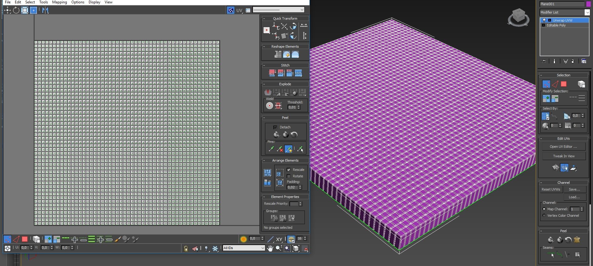
As you can see, the cubes doesn't touch each other on the UV map, and there is a very specific reason for this, we don't want the values later in the material to bleed over other cubes - remember, we divide the UVmap into sections based on how much cubes we have, so later each one will get one flat value for its movement.
What I did to "automatically" get this uvmap:
1 - place a plane, divide it based on how much cubes you'll want.
2 - detach every section into an element - you can select every secondfull rows , detach and then do the same with the columns...
3 - select all elements, and scale them down some, by a value that you'll remember...Like 50%
4 - if you started with 100x100 cm plane, now apply 100x100 cm plane UV mapping. So, same sized UVmap as how the original plane was.
5 - select all elements again and scale them back to their original size
6 - Extrude the sides, apply bevel
7 - Done
You are done
If you did everything correctly, you should get something like this:
 https://www.youtube.com/watch?v=XSrG4sQwGOo
An important thing to mention:
If you make them moving too much, they will likely go out from the bounds of the mesh, and you may start seeing a flickering/disappearing mesh glitch. To get around this, you simply need to extend the bounds of the mesh more. You can do this by selecting the mesh in the level, and on the details panel search filed, type "bound". You'll find the bound scale, set it to a higher number.
References:
https://www.youtube.com/watch?v=Ld_peIKWE3Ahttps://videohive.net/item/abstract-surface-of-moving-cubes/18266215
https://simonschreibt.de/gat/pintable/
So the result that we are looking for , is to get some cubes moving on Z axis up and down based on a noise pattern, while not distorting them, meaning that they won't change shape, but they will change their height position.
So lets start with the very basics and break down how we can achieve this:
Its all about the uvs, and how are the values distributed. Regular UV coordinates can be represented with a 2 component vectors, 2 gradients. A horizontal one, and a vertical one. Technically they could go infinite but (or the limitation of 64 bit values?? I'm not sure) you usually sample 0-1 area , or a bit more around it when you are tiling with UVs...
This is how regular 0-1 range UV coordinates are represented using a 2 component vector:
If we separate the U and the V (red and green channel), we get a horizontal and a vertical grayscale gradient. Now this is good, for continuous mapping, when you want to use the actual resolution/properties of the texture.
By adding "game time" to the coordinates, we get a panner - lets say we sample U 0 V 0 point but then on the next frame we add elapsed time or a division of that to the coordinates so the original U 0 V 0 point moves to an another location, lets say U 0.1 V 0.1, so you get a moving texture as the game updates each frame.
This is good, now we can move our noise texture that will drive the material animation. But...If we would simply pan a noise texture with these uvs, and we would take the noise values as height information, we would get the the cubes following the noise shape - distorted. So we need to do something against this.
By adding the time to a continuous value elevation, we get panning, but if we add time to "stepped" values like this, we only get value change, but not position change, and they remain stepped, rounded values:
This is much more ideal for what we want, since we divided the UV map into as much "sections" as we want, as much cubes we use - In this example its 10x10
To get this effect we need to do some simple things with the coordinates:
Then as its shown on the last image, when we add time, now we are good and we got the result that we need.
To set this up you need to do this:
Or if you are using the "custom node" then you can use this code:
return floor(UVs*CubesPerSide)/CubesPerSide;
To add the game time part, do this:
Unfortunately I don't know the hlsl equivalent of time so no code example here...
....
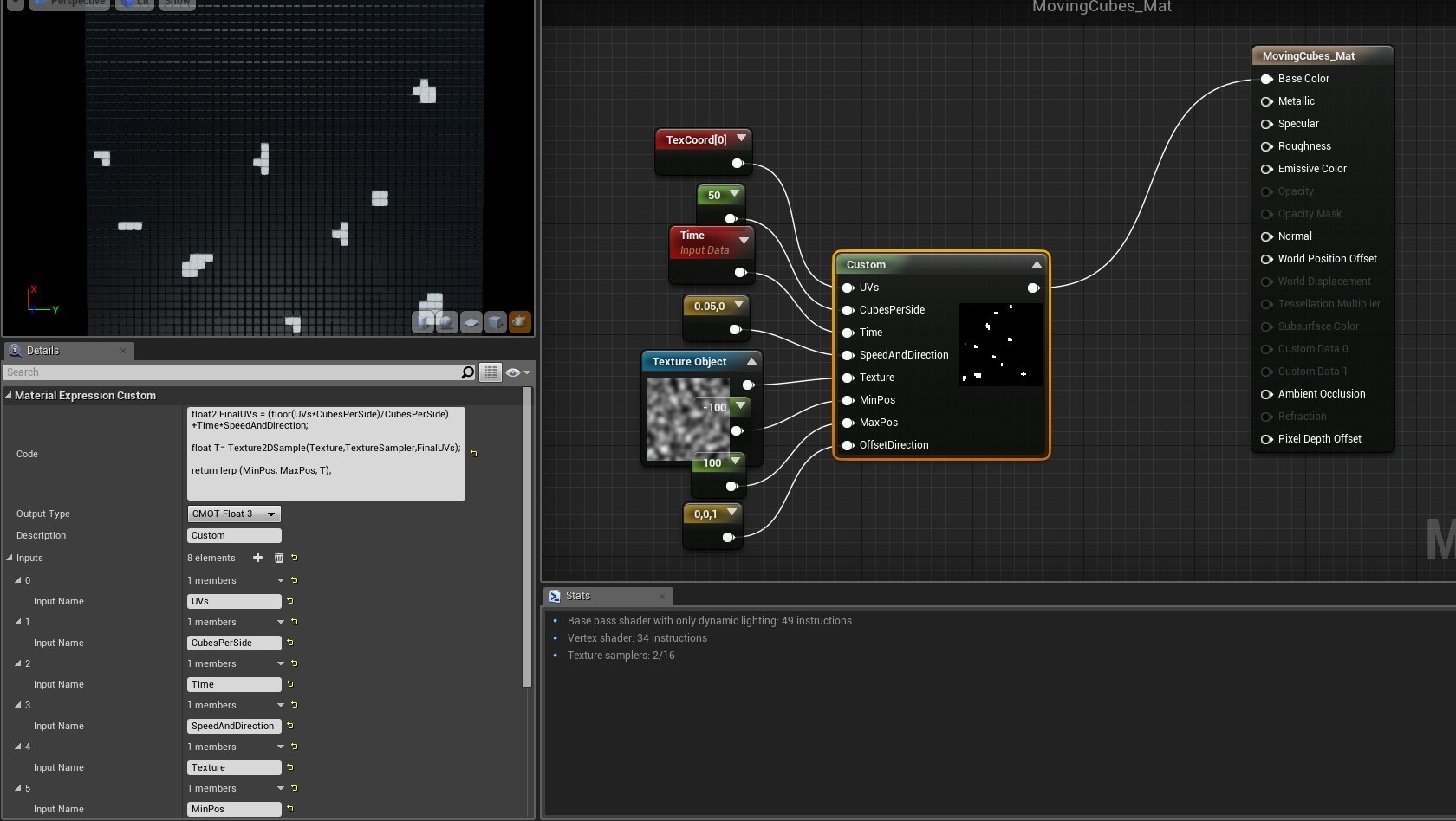
Then this UV setup goes into the UVs of a noise texture..
And this is how our noise textrue should look, when we apply the final uvs:
Then we use the noise texture, to lerp between min and max position values, and also we multiply it by 0,0,1 that is the world direction, so it will animate on that axis:
At this point, the animation is done, and the full material looks like this:
And the full code, but unfortunately you can't use texture inside the custom expression, on the vertex shader
I'm not sure why, but I remember in UDK you couldn't use at all...
I posted a question on answer hub.
Full code:
float2 FinalUVs = (floor(UVs*CubesPerSide)/CubesPerSide)+Time*SpeedAndDirection;
float T= Texture2DSample(Texture,TextureSampler,FinalUVs);
return lerp (MinPos, MaxPos, T)*OffsetDirection;
Sad story...
Notes:Sad story...
- Used 50x50 cubes
- I made it going between 100 and -100 compared to their original location
- I used a static noise texture but it works with the built in dynamic noise as well - I'd not recommend to use that because you'll end up having hundreds of instructions on the vertex shader, maybe even more depending on the noise generation settings.
This was the material part of the effect, there is a little thing left to do, and its the mesh and its UVs:
As you can see, the cubes doesn't touch each other on the UV map, and there is a very specific reason for this, we don't want the values later in the material to bleed over other cubes - remember, we divide the UVmap into sections based on how much cubes we have, so later each one will get one flat value for its movement.
What I did to "automatically" get this uvmap:
1 - place a plane, divide it based on how much cubes you'll want.
2 - detach every section into an element - you can select every secondfull rows , detach and then do the same with the columns...
3 - select all elements, and scale them down some, by a value that you'll remember...Like 50%
4 - if you started with 100x100 cm plane, now apply 100x100 cm plane UV mapping. So, same sized UVmap as how the original plane was.
5 - select all elements again and scale them back to their original size
6 - Extrude the sides, apply bevel
7 - Done
You are done
If you did everything correctly, you should get something like this:
https://www.youtube.com/watch?v=XSrG4sQwGOoAn important thing to mention:
If you make them moving too much, they will likely go out from the bounds of the mesh, and you may start seeing a flickering/disappearing mesh glitch. To get around this, you simply need to extend the bounds of the mesh more. You can do this by selecting the mesh in the level, and on the details panel search filed, type "bound". You'll find the bound scale, set it to a higher number.
Replies
Code:
return lerp(Offset,Offset*-1,sin(distance (floor(UV*AmountOfCubes)/AmountOfCubes*SineLength,SineLength/2)+(Phase*Speed))+1/2)* float3 (0,0,1);