Tutorial - Create stylized textures in Blender

We will see in this guide how to create a stylized texture of professional quality for a video game. We will need to combine four types of texture that will allow us to obtain a greyscale image as a basis to add color. The technique that I presented you will have a stylize texture (a 3D cartoon side) similar to the game Overwatch .
I created a tool to generate your gaming style and textures in one click here: linko.projects.free.fr/gametools.zip
often the textures used in video games
The four textures we will need are:
- Ambient Occlusion: ambient occlusion will create shade on nearby areas and leave the rest blank permetre this will have a shadow on the model that fits all types of lighting and improve the visual the model.
- Bent map: Bent map is not mandatory, it is used to simulate a directional light, generally from above like that emitted by the sun. We will see how to create.
- Normal map: the normal map will record the depth information of your detailed modeling on a version with few polygons will be exported in the game it will be used to simulate the relief and recover a maximum of detail while improving performance..
- Cavity map: the cavity map is not essential, but provides a design effect hand to your model so to be in themed games such as Overwatch and Dota. This map also allows to highlight small details in contrasting.
Preparation for baking
Before placing your baking you need:
- a high poly model, a detailed version which is not used in the game engine, but only in Blender)
- a low poly model is the optimized version of the game engine, you must have unfolded its UVs
The margin of UVs
When you unfold UVs U> Unwrap a Margin option will be visible in the menu of left t ask you to indicate a margin is the space between the islands UVs. Open the UV / Image Editor to see the changes on your UVs.
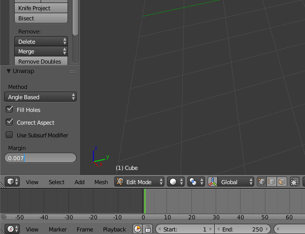
The space between the UVs will overflow the baker outside texture UVs for the seams are not visible.
Enable GPU baking
We will use baking cycles to achieve its textures, because it allows the use of graphics and ambient occlusion is good. To use Cycles Render Cycles put up the interface instead of Blender Render. To enable the GPU rendering done File> User Preferences ... in System enable CUDA. Then the options to the right of the rendering engine change CPU to GPU Device line.
Cycles options baking
baking options that is at the bottom of Cycles options menu.
Option: Selected to Active
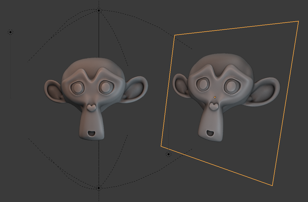
An essential parameter is Selected to Active need to project check the details on the current selection so the poly high on the low active poly (light orange).
For a selection is active it must be selected in second. Right click on your high poly then shift + right click to select your low poly.
Option: the margin / padding edge
Margin in the baking options defines the number of overflow pixels. I advise you to use 10 pixels for a texture 2048x2048 pixels and 20 for a map in 4096.
Option: the cage
The cage will perform extrusion of your low poly to encompass your entire poly high without which intersections will not Baké correctly. We must ensure that the cage barely bigger than the high poly to prevent warping. To indicate what value, I advise you to apply a Solidify change, to offset 1 and adjust the thinkness in now shift to change the value accurately. Copy the value for the cage and remove the change.
the Baking
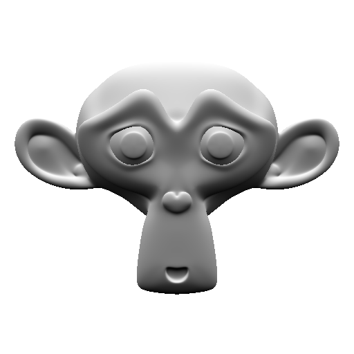
For this demonstration I'll add Suzanne (the Blender monkey) for poly high and a plan for the low poly like that you can follow the tutorial and do the same as me. As it is a plan which I have placed as to have no intersection with Suzanne I can leave the cage and the margin to 0 to 0. Set the samples for baking in Render, the default value is 128. for the normal map and the map bent you do not need a high value, 5 samples is sufficient. For ambient occlusion you can leave 128, even if you still have the noise I will show you a low technique to remove.
Make a habit of saving your images into .tga (targa), they compress too without degrading the image and allow access to the alpha channel (transparency) separately unlike .png.
You must create an image on which baker then attach the image in a material. Open lme UV / Image Editor, click New. Whatever the color of the image or is transparant or not Tnat that Clear is checked in the baking options. The most important parameter is the resolution, in this tutorial I will show 4096x4096. I'll call "4K".
By unchecking Clear in the baking options the old image is deleted, it is useful to create a sprite on a map and plan several animated versions and different angles of your low poly.
Create a new material for the low poly and made Shift + a, Texture Image and specify the path of your image on which Baké. Do not tie the other node. If you have multiple node Texture Image Cycles baker is on the active node, the last selected.
If the nodes do not show is that you are compositing node in the bottom menu you View, Select, and Add Node right and just three icons to move the nodes of the materials as compositing.
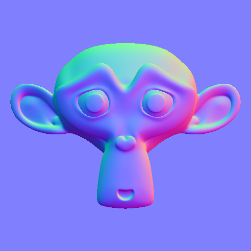
Baking: normal map
Select the high and low poly maintaining shift. In baking options he wrote Combined line Bake Type, set Normal, verify that either Tangent Space and axes + X + Y and + Z.
Baking: bent map
Bent map for baking stay in Normal mode, turn on Space Object instead of Tangent. For the axes in order to use the same as in other 3D software set + X, + Z, -Y.
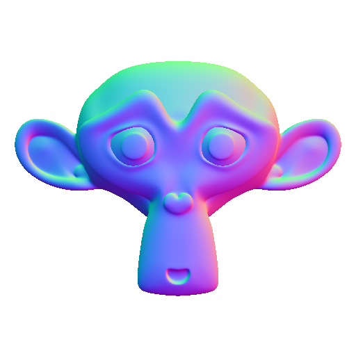
The texture is identical to the normal map because it is Baké from a plane, but with a low poly more complex it will be different from the normal map.
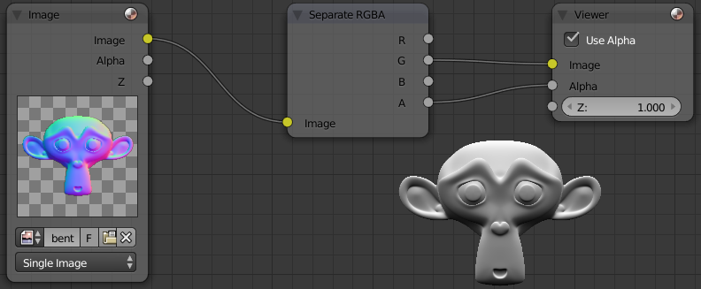
Check out the map of lighting from above
To generate a map of the lighting of the above, we must separate the colors and keep only the Green channel for lighting from above. The Red channel gives a lighting of the right and the Blue Front.
In the node editor go in compositing mode, activated the backdrop to see the result in the background. Create a node by Image Shift + a then Input> Image, attach the node to a Converter> Seperate RGBA, connect the output G (Green) to Output> Viewer. You can also connect the Separate RGBA alpha to alpha of the viewer node for transparency supported, but will not change the 3D model.
To save the image open the UV / Image Editor and Image Viewer Node turn then press F3, and save your image targa. Put RGBA instead of RGB in the lower left options to preserve transparency.
Baking: ambient occlusion (AO)
Bake in the Combined type switch, adjust the number of baking the samples based on the noise. I'll let 128.
Here is the map that I get:

Improve ambient occlusion map
Default Cycles ambient occlusion is not quite contrasting and often the noise (grain). Create a node and Image viewer node as earlier. Add two Color> RGB Curves between. On the first left click to add a point and set it coordinated X: Y and 0.65: 0.35 That will contrast the ambient occlusion. For the second RGB Curves click Black Level, switch to HSV fashion (Hue Saturation Value Hue Saturation Brightness in French) and 0.145 V put this allows to make dark parts darker gray contrasting to the edges of the map. Here is what it looks like for now the map, it remains to remove the noise:

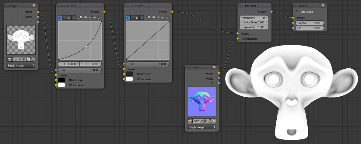
To remove the noise, add a Filter> Blur Bilateral after both RGB Curves. We will use this node to blur the image, but we want some details are not blurred (borders, important angles) you add a node picture open your Normal map that contains information angles and connect it to Determinator the bilateral Node. By default the space sigma option to blur the intensity is too high, I suggest you put 0.5 instead of 5. This is what how nodes are connected:
The technique of bilateral noise can be used for lighting by putting baking the bake-type combined. Since it will be possible to map normal baker if Selected to Active is not enabled you can instead use a bent map.
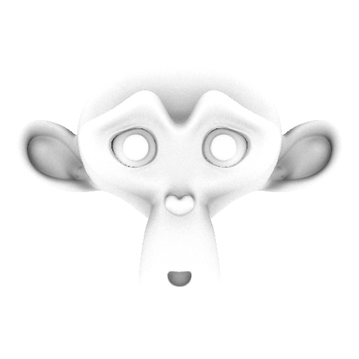
Here's what looks like the final version of our ambient occlusion map:
Compositing: Cavity map
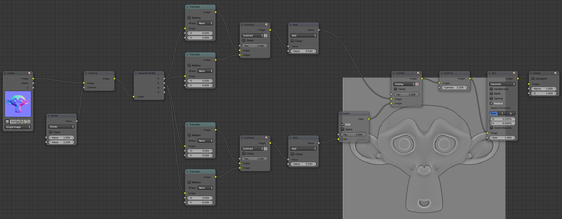
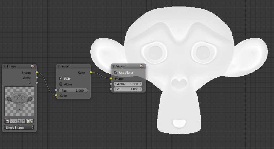
It is not possible to baker a cavity map, we will use the normal map and use multiple nodes and extract the map. To create a cavity map we will create an effect "Emboss", allows Photoshop to do it directly in Blender must be created using a combination of nodes. I hope that in the future a node Emboss available. The emboss the image will move in a direction in a number of pixels that you set. A picture will be moved to the left one and a right node identify the differences between the two images to draw the edges of the image. We will do this by moving the image up and another version moved down but for this version it will invert the colors.
In the compositor Blender import your normal map with the Image node. To reverse the image is not enough to use a node in Blender Invert must change the gamma otherwise the image might more generally darken or become clearer with even a medium gray (Value at 0.5 / 1).
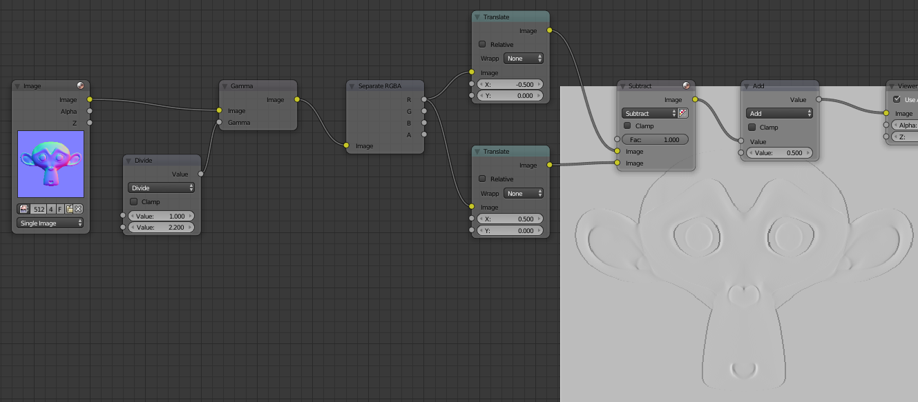
You can lean on the image below to help you create your nodes. Add a Color> Gamma. Create Converter> Math put the Divide in fashion to the first line put 1 Value and the second 2.2. Connect it to the Input Gamma. Connect the Gamma node to Concerter Separate RGBA. Add two Distort> Translate, connect the R channel to each image Translate node. Put X -0.5 to one of nodes X and 0.5 (by moving half a pixel on each side yields a total gap of one pixel). Create a Color> Mix, tie the two images and switch to Subtract mode to highlight the difference between the images. Tie a Converter> Math Add mode and set the value 0.5. That looks like our nodes for now and the result you should have:
Add two Translate node that you connect the green channel, this time to 0.5 Y and the other at -0.5. To put X 0. Then you do the same as before, connect the two nodes to a node then Subtract Add a node. You can duplicate nodes with Shift + d. The difference is that you need to add a Color> Invert node after node Add. Gather the cavity with the X in Y with a Color> Mix node in Overlay mode and return to the original node put a medium gray Color with Gamma value to 2.2.
The cavity map is almost finished, if the resolution is low baking you a little aliasing on the edges (stair effect), to remove this effect add a Filter> Blur node check Relative which will allow to enter not a pixel value in% but that will fit all image resolutions. I put 0.1 or 0.05 in order not to blur the image and keep my details while removing as much as possible aliasing.
You can make the map more visible Cavity increasing values Translate. Instead of 0.5 and -0.5 You can put 1 and -1.
Compositing maps
Generating a grayscale
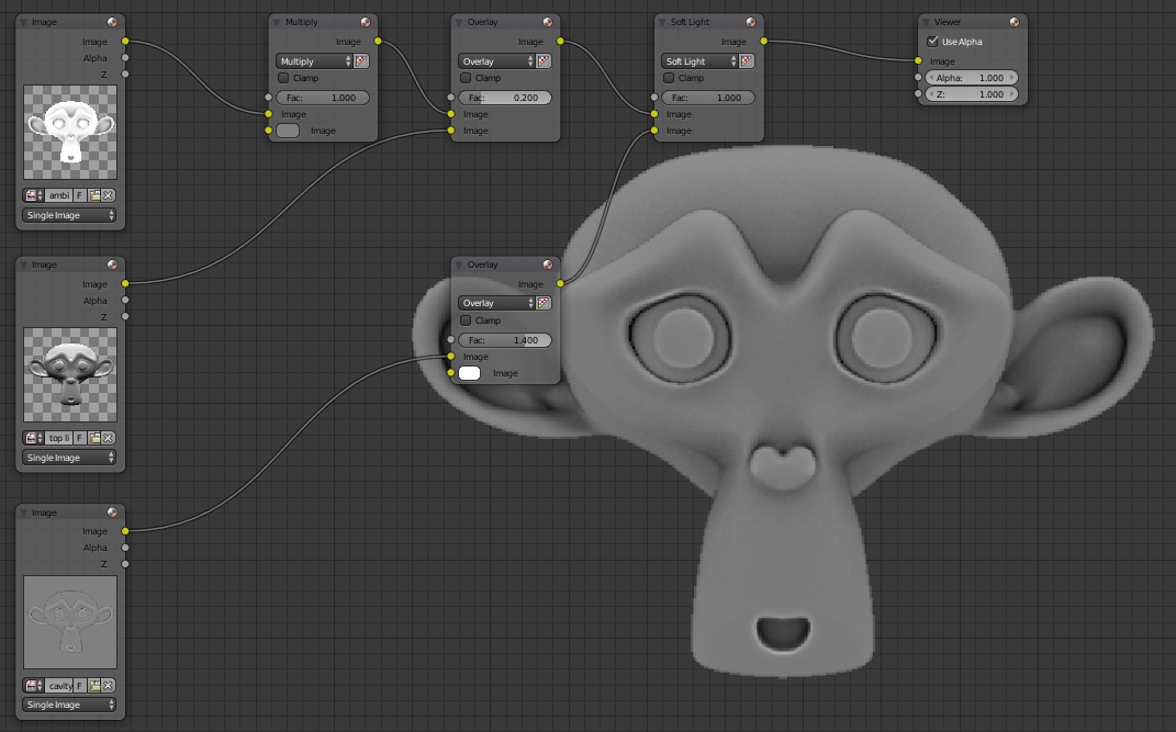
We will combine ambient occlusion, map lighting from above and the cavity map extracted from the normal map to generate a greyscale image as a basis for our texture. I'll show you later techniques to color. The normal map will not be used for grayscale, it will be applied directly to the model to simulate the relief.
Import the ambient occlusion, top lighting and cavity map in the compositor. You will intoxicate the ambient occlusion map, for it made Color> Mix, put the node in Multiply mode, attach the image and replace the white color with a medium gray to HSV mode and entering the Value 0.5. We will combine ambient occlusion and top lighting, created a Color> Mix in Overlay mode, tie up the ambient occlusion and below the top lighting. Use the factor to make light of it more or less visible, if it is too visible texture will not be realistic if the lighting of the game comes from below. Put a small value such as 0.2. Combine Cavity map by putting a Mix node type Soft Light. The cavity will darken your map texture set between Mix Overlay mode with a 1.4 value for the cavity is clearer.
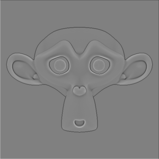
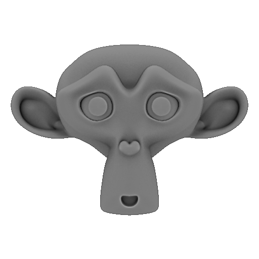
That is already finished we have the basis of our texture:
Here is the basis of our texture:
Save your grayscale.
Previewing his playing style
Just go to colors, but before we'll see what gives the low poly with the applied texture.
Switch to Blender rendering Render, select your low poly, remove the material and create a new one (the other only worked Cycles render). Go to the Texture tab. Click New, load your Grayscale.
In the 3D view switch to Texture mode, this icon at the bottom right of Object Mode. Add a lamp.
- If the texture does not appear n open the menu of the 3D view, shading to change Multitexture by GLSL.
- If you want your texture is transparant the options texture tick while low alpha and color in Specular.
Import normal map by selecting a new texture slot and then clicking New. Load the texture and the bottom options and uncheck Color Select Normal in Geometry. A little earlier in Image Sampling check Normal map as Blender uses the map as a bump map by default (map in gray tone that pushes the relief in a single direction).
That's what happens to recall my low poly is a plan by importing the grayscale and normal map light reacted as if there was relief yet everything is flat there is only one face:
For lighting I use two Hemi light that facing down with an intensity of 0.4 and that facing up to 0.1 to simulate the bouncing of light on the floor. I added a two lamps with a warm color orange and blue with a cool color. I use the HSV Saturation to adjust the intensity of the orange and blue.
Color grayscale
There are several ways to color a grayscale, the simplest be painted one color and mix in overlay and soft light. The colors will be too simple, instead using a color ramp (also called gradients) you will have several colors that change depending on Gray Value.
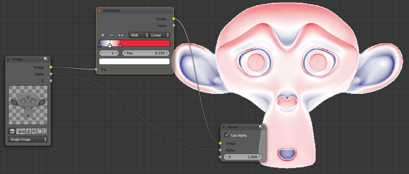
An example, by importing your grayscale in compsitor and adding Converter> ColorRamp you can change the color that will be allocated to black to white. An example if I put everything on the left a blue color, a red right and I added a slider to center by clicking the "+" and then you move the sliders to the left a gradient with the colors used between colors.
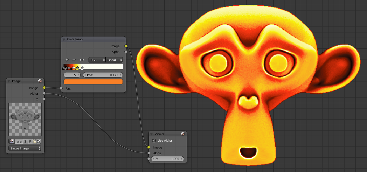
You get the idea, it will adjust the value for the black parts have darker colors. By selecting colors on an image taken, for example by typing Lava on Google, I recreated a lava effect on Suzanne. That's what it gives me, imagine having to paint, you gain a lot of time with this technique:
To retrieve the colors in an image open the UV / Image Editor, switch to Paint mode and open the menu T. Place the cursor on the color recovered and press s, the color in the left menu will be updated, put the cursor at the top and press Ctrl + c to copy it. Come back in the compositor, select the cursor which applied color and made Ctrl + v above the box for color.
Masks
The gradient map is applied to the entire image, but you can use a mask to only use it on one part and create more materials (some skin, another eye, etc.).
To create a map go to the UV / Image Editor, display the texture node viewer or grayscale and switch Mask mode instead of View or Paint. To create the points of the mask must be a Ctrl + left click, if you hold the click and move the mouse you will create a curve. To change the type of point you can select one and press V, the type will Vector a straight line and a curved Aligned Single. The mask is automatically closed between the first and last point. To create a new mask deselect items with the a button and place new items.
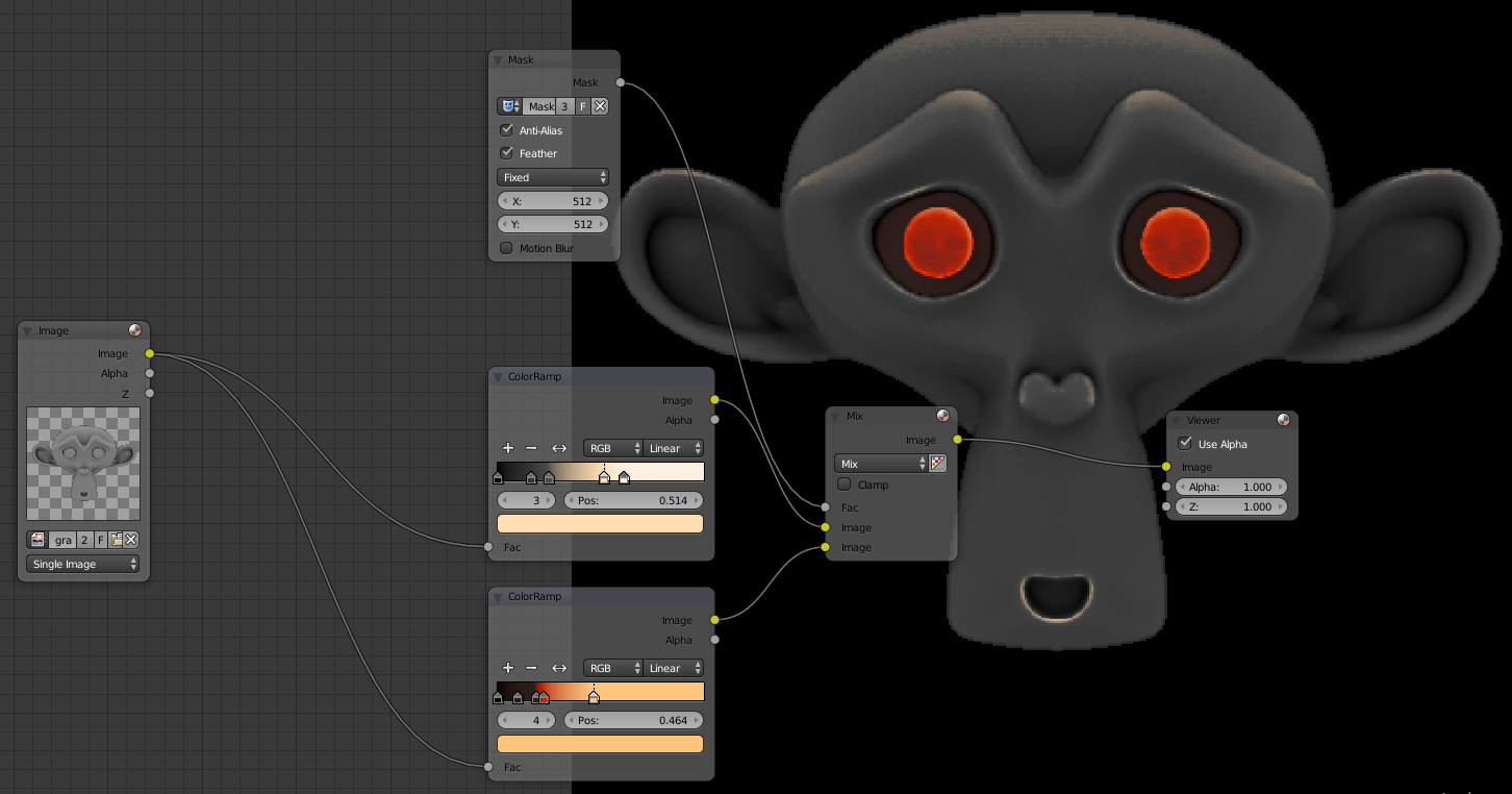
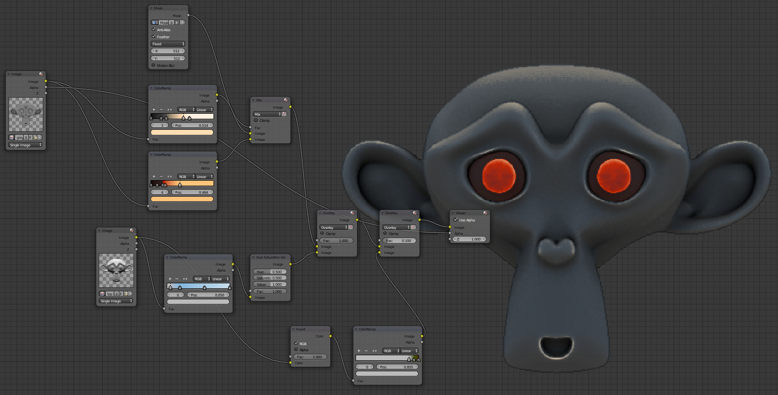
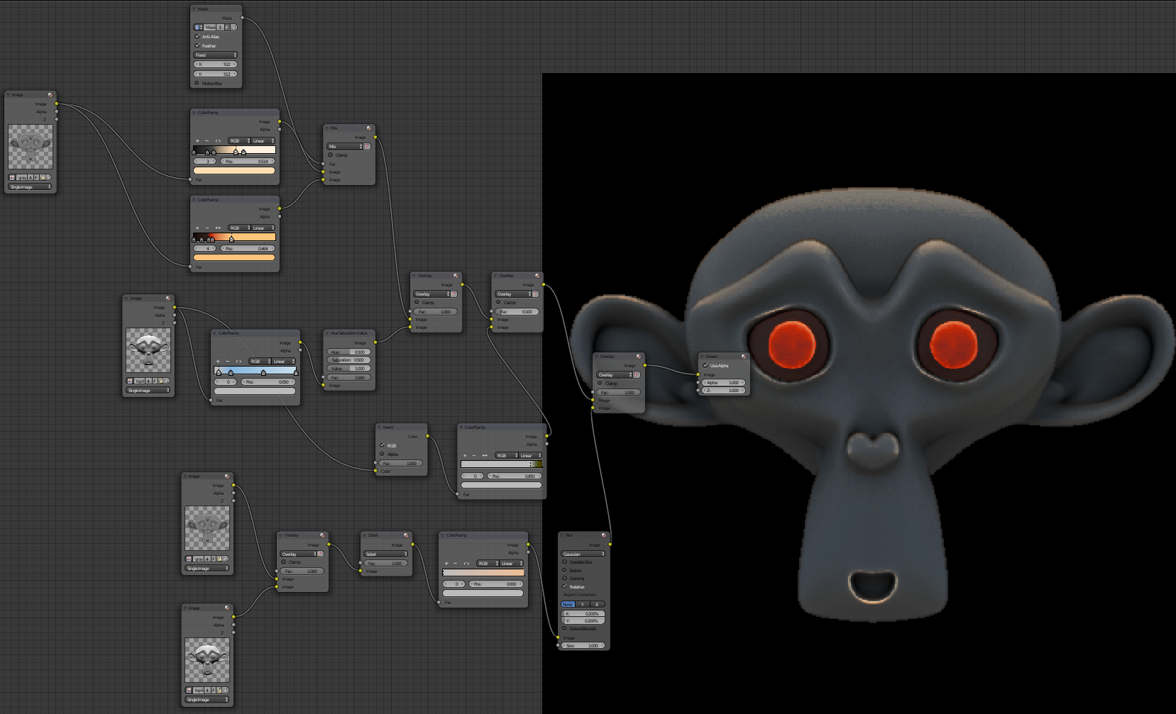
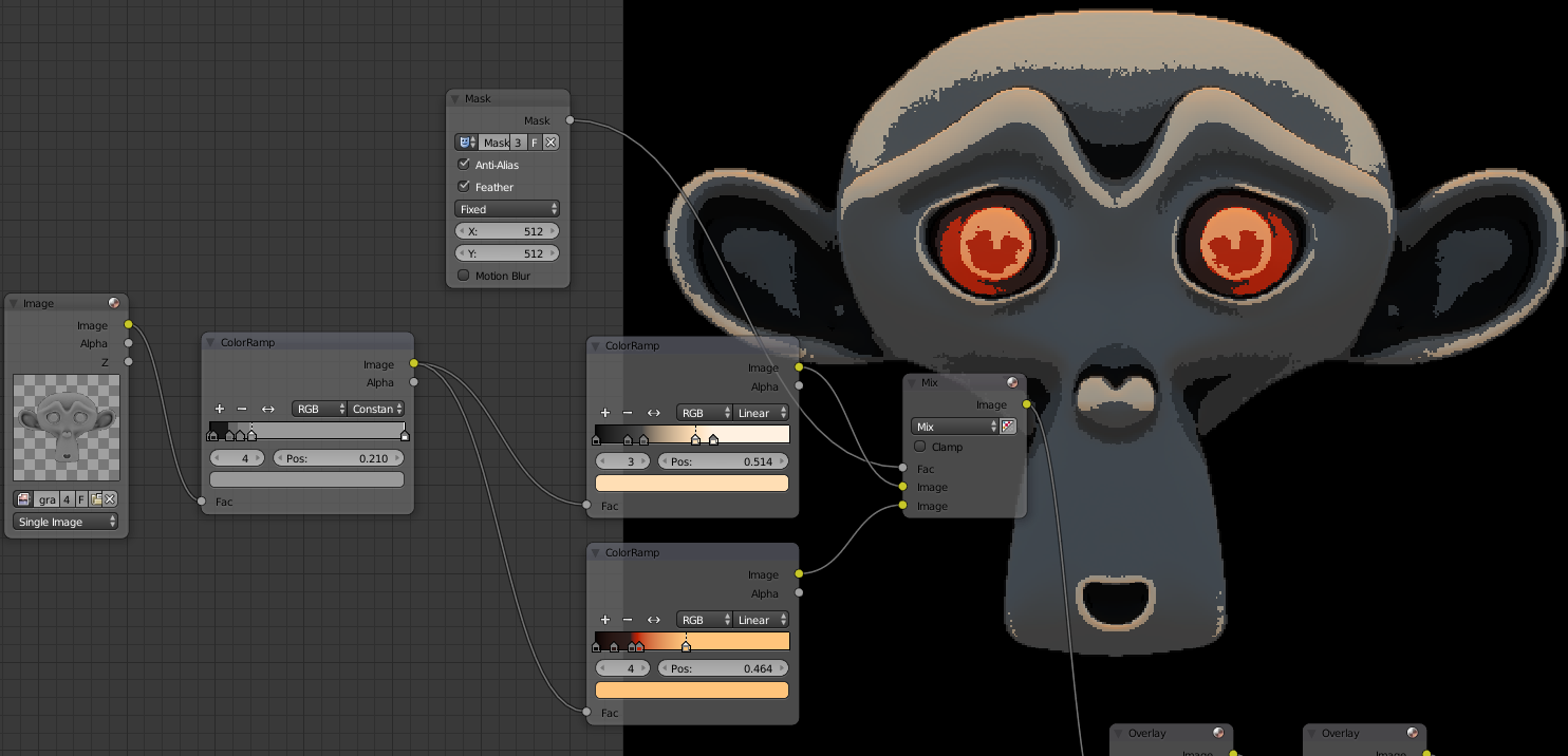
To use the mask in the compositor made Input> Mask. Select your mask by clicking on the blue icon node, select Anti-Alias to limit the staircase effect, change Size Scene-by Fixed and enter the resolution of the image. To use add a Color> Mix node, attach the Mask node to the factor, for the first frame put the previous image below, in our case it is the source grayscale. By putting the image above, this will combine multiple gradients. The node must ColorRamp him always be connected to the source which is the grayscale:
You can only fully with gradient color your model. I advise you to create a collection of color ramp to reuse in your projects. To import a node of another project first create a group with Ctrl + g and name that you will use it in another project. To import do File> Append, enter the blend in NodeTree and select the group. To create the compositor made Shift + you will see in a Group.
You can use a Color> RGB Curves to adjust the contrast of your colors.
Bonus: visual effects
We'll see how to add some effects on our texture to improve it.
global illumination effect
We will simulate outdoor lighting using our lighting picture above.
sky lighting
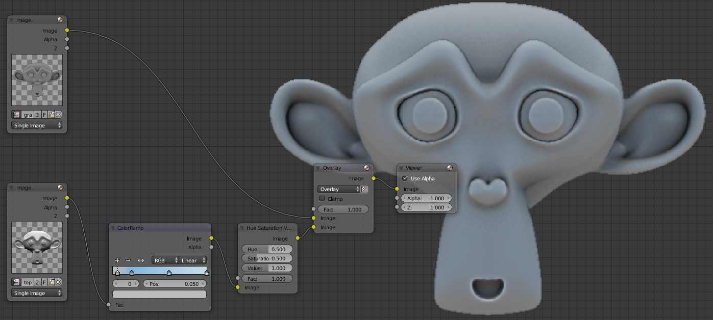
To simulate the lighting of the sky is very simple, recovered a picture with interesting sky color to retrieve your Converter> ColorRamp. Attach the ColorRamp Top Lighting to the image and add a Color> Hue Saturation Value to saturate the image by reducing the value of Saturation to 0.5 by example instead of 1. To add the use Grayscale Color> Mix mode overlay and change its factor, I put it at 0.4.
Ground illumination
Bounced light on the ground we have lighting from below. Our Top Lighting texture is illuminated from below simply by inverting the colors with Color> Invert. Collect a picture with what you want as soil type: grass, wood, etc and put the colors in a new ColorRamp attached to Node Invert. Mix the previous image in overlay mode with the lighting of the ground, put a smaller value than the sky factor, I put 0.1.
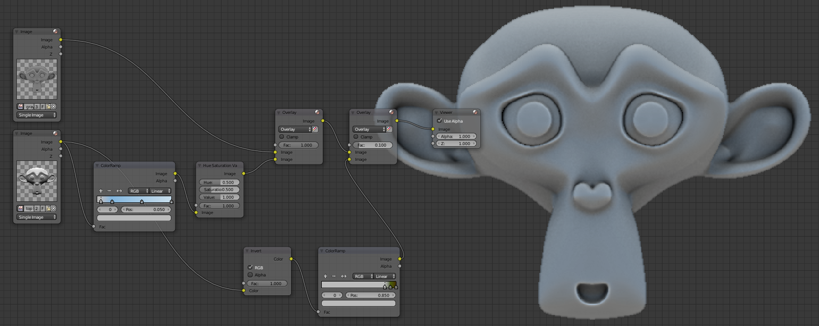
You can conneter the colored image to the first Mix node for global illumination and colors at once:
Add soil
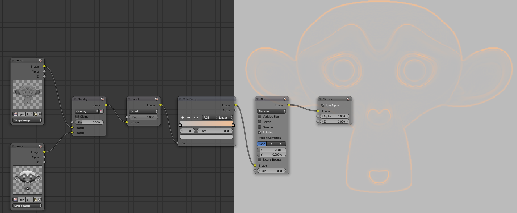
To add to the earth we will combine ambient occlusion and top lighting this will have land in the valleys but also on top of the surface for more realism. Use Overlay to 1 by connecting the ambient occlusion above. Add a Filter> Filter and set the fashion Sobel it will highlight stops the white model. Then connect it to a ColorRamp to bring him a light earth color (beige) on the right cursor. For the cursor left turn white with a value in 0735 so that it does not modify the image (not to make it lighter or darker). Then add a Filter> Blur Relative mode with 0.2 X and Y. This is what you should get:
Use Overlay for combining land with colored grayscale with Global Illumination. The factor determines the amount of land.
Here is our final texture:
Effect of Cell Shading
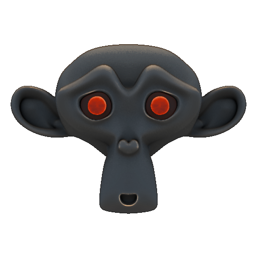
To create a Cell Shading effect place a ColorRamp just after the grayscale in Constant mode instead of Linear and put several shades of gray:
This technique also gives a badly compressed effect as in the retro games and give some style to it.
Bonus: reduce the size of an image and change its ratio
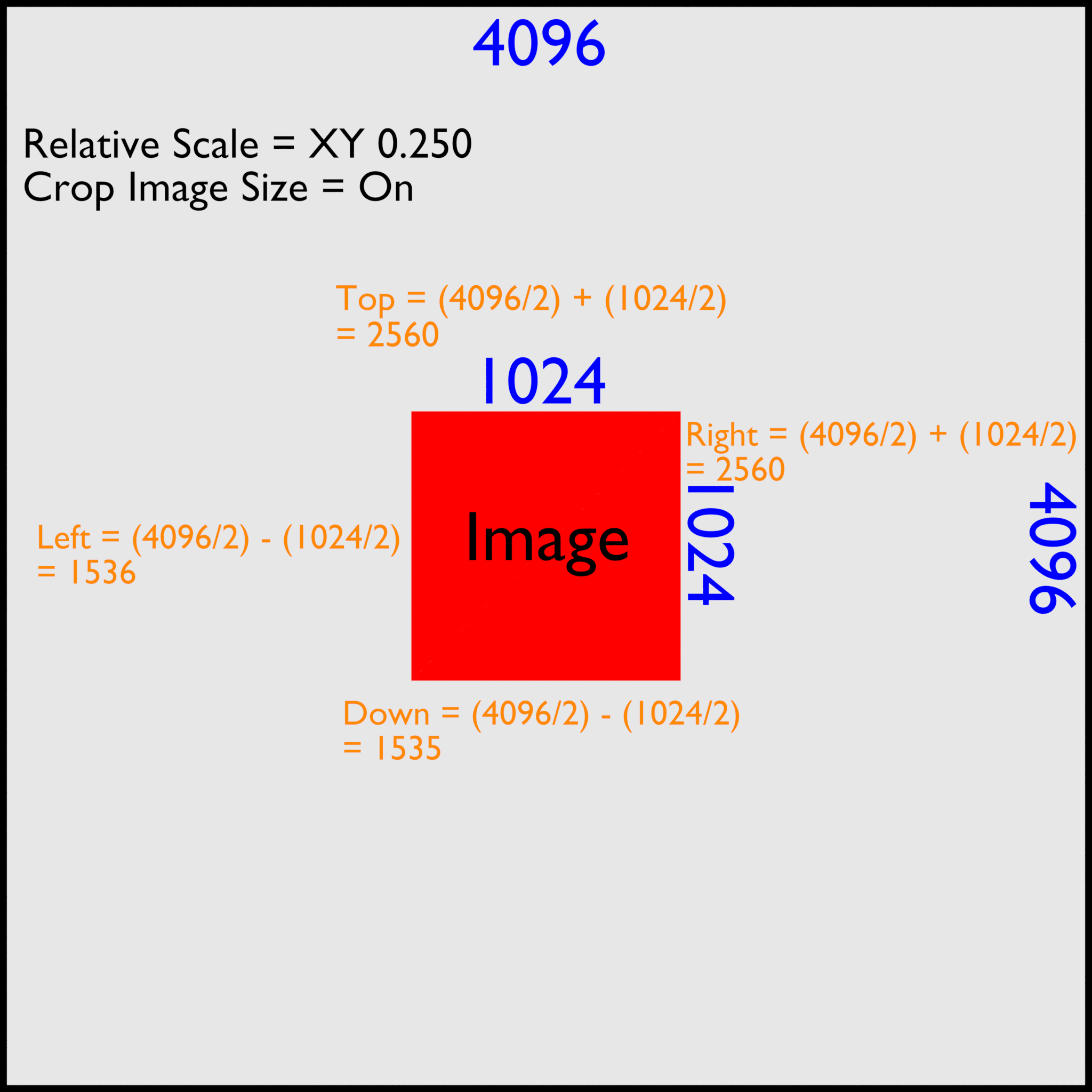
The baking this often in 4096x4096 or 2048x2048, but these resolutions are too high for video games (except for lightmap). In the compositor should be used Distort> Scale node, verify that you are in Relative mode. To place an image in 4096-1024 divide the size by 4 so put 0250 for X and Y. The image is resized, but not its edges, it always 4096. You must add an Distort> Crop and check Crop Image Size. To calculate remove as divide by two the total size of the picture therefore 2048 and halve the size of the new picture 512. Then you must withdraw 512-2048 for the left border and the bottom and add to that the top and right. I made a diagram:
Bonus: invert the colors of an image
By default if you use the Color> Invert Blender image generally become either too light or too dark even using a medium gray which should not normally change. By reversing the colors of the grayscale image becomes all too clear:
To invert the colors we will always use the Node Invert but use other nodes simultaneously. We had to reverse to the Green channel of the normal map to generate a cavity map.
To invert the colors must change the gamma, invert and restore gamma. We must create a node Color> Gamma and attach the image reversed in Image and tie underneath a Converter> Math Divide mode with the first line 1 and the second 2.2. Then put a Color> Invert node and another node with gamma value to 2.2.
The colors have been reversed:

Replies
Adding it to the mega thread..