It starts May 12, and ends Oct 17. Let's see what you got!
https://polycount.com/discussion/237047/the-brawl²-tournament
Alex's Texture Scans

I decided to try my hand at capturing textures with a cross polarizing light setup and this was the result of todays test.


I generated albedo, normal and specular/roughness maps.
- Canon 7D
- Canon EF 28mm F1.8 USM
- B+W Circular Polarizer
- Canon 430EX II Flash
- Manfrotto 055XPROB Tripod
- 1 Sheet Linear Polarizing Gel
- NEEWER 160 LED CN-160 Light (Cheap Shit)
- Remote Shutter Release
- Threaded Light Stand
- I setup my tripod to full height and used this cool feature where you can convert the stem from vertical to horizontal, so I could shoot downwards.
- I then got a small square table which I put a plain black piece of cloth onto so I can have a nice matte background, and be able to tell when my the cross polarization works.
- I cut a few pieces of the polarizing gel so it would fit onto my led light and over my flash using cardboard and duct tape.
- I dial in cross polarization by using a coin or washer, as I adjust the reflected light from the coin changes, when it is at it's darkest you're set, you can also see the matte cloth go dark too.
- My first shot is the using the flash only cross polarized, then I rotate the gel on the flash 90 degrees to get the second shot (I set the power low to sort of match the led light).
- Next I use the light only, I have it pointing down at angle, I take 4 shots moving the light around in a circle so I end up with a bottom, left, top, right, then I rotate the gel and repeat. (Each time I position the light 90 degrees the shot goes into or comes out of cross polarization, so the order of images I end up with is bottom-pol, left-spec, top-pol, right-spec I rotate the polarizer on the light 90 degrees and then get bottom-spec, left-pol, top-spec, right-pol).
I am left with 10 images, first I bring them into photoshop, label and stack all into a single file (I should have brought into lightroom and done lens corrections etc).
Then I extract the specular of each direction by overlaying the image with highlights over the one without highlights (cross polarized) and setting the layer to difference.

As you can see, it isn't perfect at A I get weird hue shifts where the leaf colour varies and overall I go not much value at B due to angle of the lights/curl in the leaf, the room was also pretty dark, so there wasn't much other light contaminating the scene.
I do this for all 5 directions, and then I desaturate and blend all the channels together using a lighten. to get my specular and invert for roughness.
I generate my normal maps using the maps except for the frontal using the method shown here http://www.zarria.net/nrmphoto/nrmphoto.html
Because I split out the specular fairly cleanly, this method actually works decently for objects with different colours along a contiguous surface.
For the Albedo, I blend all the 5 cross polarized images using lighten.
I brought my albedo, roughness and normal into substance designer so I could tweak things. I did have to brighten the albedo a bit I'll get a colour chart to do this more accurately in the future. It is important to not blow out the highlights on the specular images, so I rather under expose the albedo, than screw up the normal and roughness.
My take aways are to get a colour chart, experiment with the light angles/softboxes, get some strong double sided tape to flatten those fucking leaves out. Ideally I would get a few more lights and stands so I could just turn the lights on and off as I need rather than re-positioning each shot.
Where I currently live there are a wide variety of interesting plants and as I refine my process I'd love to share them, maybe throw them up on gumroad or something like that.
Replies
Thanks. I did some experiments with regards to my specular stuff and the missing highlights were due mostly to the angle of the light. So I'm going to try to do a 45 degree angle, and an almost 90 degree angle (a bit less to avoid self shadowing).
I've ordered a few more things, including some plastic material for me to make holders for the linear polarized gel. so they can slot into the front of the led lights. I figure by rotating the filter for each position, I make sure the light is in the same exact position for the cross polarized and specular shot, and I move the light stand around half as much, so less chance of bumping something and having to start over.
I'm also going to shoot tethered in lightroom, even though I have a shutter release cable (The short one) because the tripod is in the horizontal position the setup is very bouncy even the slightest tension difference on the cable has it moving.
I'm also ditching the flash for the time being, and instead lighting the frontal shots with 2 of the led lights. The flash isn't really able to give me the even coverage I need throughout the whole frame, but that setup is still decent for field capture.
When I get the new gear I'll post results and picture of the setup for anyone who's interested.
This is part way through the process of making holders for the linear polarizer gel, basically it stiffens up the edges so I can put it in the light filter holder easily and thus be able to rotate them easily.
And here are a few shots of my setup (pardon the crappy cell phone pictures).
This is my "frontal" shot, the lights clamped on the bottom aren't being used for these.
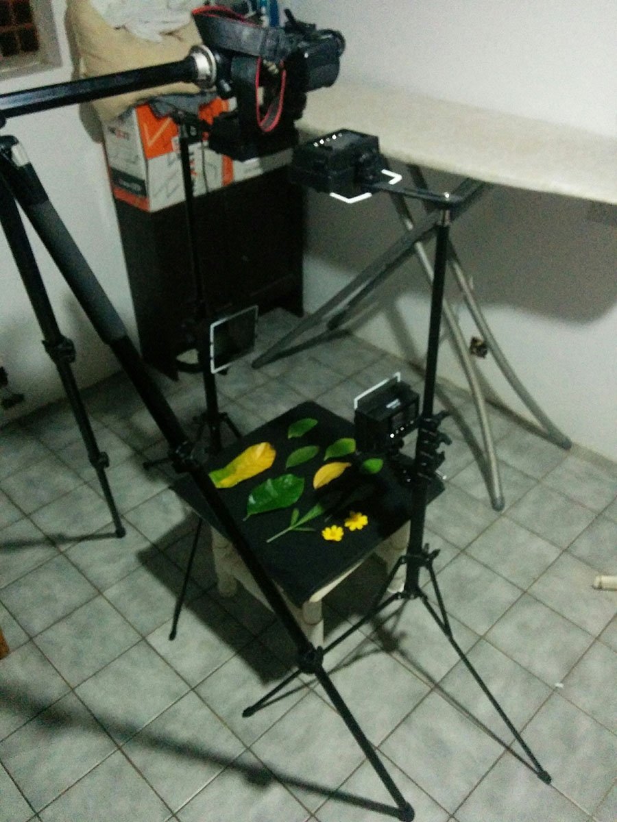
And here is my Top/Bottom setup

Here's a dropbox link with png versions of the Albedo, Roughness and Normals.
https://dl.dropboxusercontent.com/u/10105386/pc/160410-Scan.zip
Let me know what you think.
I also need to test a few other ideas I have for lighting.
So hopefully when I get more time I'll pick this back up.
So I'll definitely keep linear colour space in mind going forward, and TBH I was adjusting levels on the specular to get it to behave how it did in real life and that is probably the issue right there :pleased:
There are a few things I need to play around with on the capture side, but things are a lot easier compared to the last setup.
Here are a few results running a few images quickly through the graph to prototype things.
I'm still playing around with methods for generating the alpha masks for these. I should try to have similar colored leaves in the same capture but then these cases where I have crazy colored leaves where the spots want to clip through pose a problem. Ultimately I think I'll end up doing some cleanup on a few of these but I'll have to see how this does for more complicated things like ferns.
I also captured backlit versions of some of these things, but not sure how to use those just yet.
On another note, Substance Designer's new multi-angle to normal node works damn well, even on the multi color leaves. The multi angle to albedo works okay, but since I'm already shooting cross polarized shots to derive roughness values I'll continue to use those for my albedo.
I have a sort of scaffolding made out of PVC pipe, which I can quickly clamp on my lights and there are 2 crossbars on the top where I mount the camera and another light. Right now the setup is 3ft cubed, but I can just cut longer PVC to be able to capture larger subjects light palm fronds, I probably won't go past 6 ft since i don't have room for much more than that. The lights are super bright cree XHP70 LEDs (I got high CRI versions also) which I mounted on aluminium heatsinks which are 1/4" threaded on the back. I found that LEDs without reflectors or lenses throw out very wide and surprisingly even lighting. I made filter holders out of some aluminium channel which end up holding a layer of diffusing material and a piece of linear polarizer.
I have a piece of translucent acrylic which the subjects are set on, and this is raise up from the floor so i can have a light for the backlighting, so far the translucent acrylic might be too transparent and I end up having to lower the light intensity, I might just try regular "opaque" white sheet to see if it does let some light through, it is also easier to get my hands on.
I have my camera mounted in one of those video cages and made some braces so the rig can sit on top of the 2 spans. I have the light clamped onto one of the spans and placed as close to lens as I can.
I'm using this Sony prosumer camera mainly so i can zoom in and out as needed since i don't have a suitable zoom for my canon 7d. I am using a linear polarizer instead of a circular, the drawback is autofocus doesn't work very well with it, but the retarder on circular polarizers that allow metering and autofocus to work result in clipped values when i subtract the cross polarized image from the specular one to derive my roughness/gloss.
I have one of these adjustable rubber gears that people use for follow focus rigs, I thickened the front element that rotates by wrapping a bunch of thin vinyl tape so when i move the handle, it only rotates that front element.
Instead of rotating filters between cross polarized and specular shots (which i would have to do on all 5 lights I just rotate the polarizer on the lens. I run the risk of moving the camera between shots but since my lights and camera are mounted to the same frame turning 5 filters like before would probably result in the camera moving due to light filter adjustments rather than camera filter ones.
I use coins or metal to verify I'm in a cross polarized position, I mark that point and rotate 90 degrees to to get the full specular effect I mark that point too so when I shoot I can just move the filter between these points quickly.
I shoot tethered to a laptop to avoid bumping the frame. My lights are powered by a lab power supply so i can have the flexibility of varying voltage and current to the lights.
I had fun wiring this little control box, it allows me to switch between each light easily using the rotary switch, I only have a 2 way switch on the front/back because I couldn't find a rotary switch with more positions to accommodate.
On my recent set of captures, I took bracketed shots 3 per bracket 1EV, next time i'll test out doing 2EV, I did this because the specular shots are easy to blow out, and if that happens the normal detail that you derive from those areas are useless.
It is a pain in the ass to sort out these files normally, but bracketed its even worse. So I try to keep the same shot order for every set and move those into separate folders as I go.
I also got a colorchecker, and I shoot my first shot using that and maintain the lighting intensity as I go, so later on I can color correct all my images with 1 profile.
Pheww that was a long wall of text, if you have any questions or suggestions, let me know.
I'm still trying to work out the opacity generation hopefully when I go through some of the other scans I can come up with something decent.
https://www.dropbox.com/s/de4u2f3bgcsydmr/HeliconiaLeaves.zip?dl=0
Sweet work with the scans. I've been working on a head scanner (and in progress body scanner) myself, and have been considering setting up a little system for materials, plants and potentially another for small props as well.
Have you considered diving in to arduino to automate the capture process? My thinking here is, depending on your camera capture software, you could easily write up a script (Python) that handles all of the exposure bracketing, and sync that up with an arduino controller that alternates the various lights that are on/off.
I haven't any experience on the arduino side but have been investigating it a fair bit for the body scanning stuff, seems fairly doable?
I also moved over to digicamcontrol for the camera software, which has a tonne of flexibility for the automation side.
Thoughts?
Initially when I was trying to figure out a method for rotating the polarizer I looked briefly into automated stuff like arduino and it honestly scared me off, although the example I looked at was to do with a constant follow focus sort of rig with 2 servos which is more complex than just turning lights on or off. My system is fairly simple at the moment so i don't think it really warrants much arduino stuff for now.
The digicamcontrol software looks pretty cool though, before with my 7D I was simply doing tethered capture through lightroom, the rx10 III I'm using now has some of it's own capture software but it's basically a glorified remote shutter because It doesn't even have any sort of preview or histograms.
I still have a ways to go and a bunch of stuff to test out with this setup but hopefully I can get there.
Good luck with your head and body scanners, sounds pretty cool.
digicamcontrol is pretty sweet. I was using SmartShooter as well for a while, but digicamcontrol is open source and free. It also has the built in options for focus stacking and exposure bracketing as well which you might find useful. Worth checking out if you get the time.
As with all things, this stuff seems to take a lot of trial and error
would you make a build guide so i can rebuild it
When I get some time I can go though any of that in more detail.
Been playing Breath of the Wild, which has eaten up a chunk of my free time.
you could sell the scan kit making tutorial on gumroad or so
hahahaha
hahahaha
Do you have an idea on how to do that or are you still pondering that yourself?
Just wanted to say how inspiring and helpful it has been to see your progress!
I'm having trouble coming up with a way to get proper specular data similar to the Emily Data (see below). Cheers
Sorry if I couldn't have been of more help, but If you haven't check out Paul Debevec's research along with many of the other research articles mentioned within, they have tried most of the crazy shit so we don't have to, and they talk about the limitations and benefits of the different methods.
Yeah for ramping up to a 3d face scan, it will take a light stage ):
He has the same issue with those examples where certain parts of his subjects are blown out and other parts are very dark not because they are super rough, but simply because the surface is facing away at too much of an angle.
Since I cross polarize all of my lights, I try to blend together the different shots in an attempt to get more data, but since those lights are at such a drastic angle anyway it doesn't add that much of an effect. Possibly if they were at a higher elevation it might be more useful but then I wonder about issues with having the polarizers out of phase.
Since I only have two lights, i did it the janky way. First to capture Albedo, I set the lights next to the camera at about 45deg and shot. Next to capture photometric lighting, move one light by hand in without xpol data. Below you can see my results... Next I wish to ramp this up to a 3d scan, so mixing photometric scan light setup with a turntable single camera photogrammetry setup. My goal is to pull a true normal/height map from each angle shot and then project that onto the photogrammetry model.
Photometric scan results -
There are multiple reasons I only have 4 photometric lights but one of them is that is is easier to have all my polarizers in phase, meaning I just have to rotate the square polarizers I cut out 90 degrees to be either in or out of phase. When you get into these 45 degree angles needed for an 8 light setup it is trickier and makes it a bit harder to setup and break down the rig.
The point i was trying to make in the earlier post is if you have objects that don't generally face the camera, there is an angle of incidence you don't really get much of a specular value at all, but if you had lighting from more angles you could combine those to get a more even specular representation closer to what you could get from a light stage. The hard part would be adjusting the polarizers to be able to get a proper cross polarized shot.
The software I use to process my directional or photometric shots is called dabarti capture. it works by using a sphere (I use the plastic cover of an led light bulb) of some sort to determine more accurately the direction and angle of lights. since I have a fixed setup I capture my sphere by itself each session and use that data to match up the rest of my shots. However another method would be to have the sphere just outside the square crop, but still photographed. What this allows is someone without a bunch of lights, to light from many arbitrary angles and use that data to generate height and normal data. This doesn't really address whole cross polarized specular capture but I though it might be something to look into.
As far as the turntable capture goes, I'm not sure how useful it would be to project the true normal/height onto the photogrammetry model, since that is kind of what the photogrammetry software does itself to generate the geometry in the first place. Possibly some sort of cross polarized setup to get the specular component, but I haven't gotten too deep into that sort of photogrammetry myself so I really don't know what's possible.
I'm planning on adding more lights and the old aluminum angle filter holders were bulky, heavy (relatively speaking) and required me to use too much polarizer material for the filter. They snap over the aluminum heatsink material that has a 1/4" thread on the back, I went a bit too big with the tolerances so it is a bit loose, but the next version will account for that.
There was some cleanup to be done on the print but overall I was happy with it, I got it done at Voodoo Manufacturing in PLA for $7.56 before shipping and they worked and shipped it pretty quickly.
Check out the damage, these were tested at full power for a few minutes which isn't typical but i wanted to stress test. They were also tested facing upwards, which seems to have a greater effect due to the heat rising onto the filter.
Only showing this proof of concept, because I'll be changing things yet again.
What I will be doing now, instead of rotating the polarizer with a motor which has issues, I will have 2 lights at every angle whose polarizer filters will be cross polarized relative to each other.
This allows me to capture quicker since I don't have to wait for the motor to spin the polarizer, and it simplifies my rig setup both physically and electrically.
I also designed the filter holders to allow mounting at 45 degree increments, so I didn't have to make a specific part for those angles.
I am also printing brackets for my cage/support whatever it is called, I am using 2020 V Slot, which is plenty strong for my needs and has endless mounting options.
I 3d printed a motor & light mount that attaches to the front of my lens where the lens hood usually mounts. While I may only mount the motor the cool thing is everything adjusts when I zoom so I don't have to adjust the motor mounted to the rails every time I adjust zoom, I can get rid of the rails all together. For fixed lighting setups like I would use with dabarti capture I wouldn't want to have the lights moving around but this might lend itself well to photogrammetry type capture in controlled lighting environment or even just capturing small objects using the multi angle to ... Nodes in substance designer.
While I was waiting for parts I went back to playing with the stepper motor idea. After I figured out the bayonet mount, I tried it out with the TPU (rubbery) printed gears. I got lots of skipping at certain parts of the gear even with the stepper driver adjusted to full power, which made me think the gears were printed unevenly. So I went off and printed my own gears in PETG, while it took me a few tries to get a good fit the gear worked amazingly. The only time I get skipping is if I mounted the motor too close to the gear, but I designed with adjustment in mind and with it dialed in I had no skips whatsoever. I cranked the speed and acceleration up 10 fold and no issues.
Since the stepper motor setup is working well and I have decided to go back to using it, I have a problem... Since I was planning on having 2 lights at each photosite, and having 16 photosites... That means I have 32 LEDs (actually more with the spares) and I don't really know where to use them. My light rig didn't really account for all of that, and I don't really want to go cutting into a bunch of perfectly good V slot only to change it 2 weeks later. So I will do a few tests and see what sort of result I get with many different angles and figure if it is worth it to have that many lights.
The first image with 16 shots,
Below with 24
And finally 32
All the images include the highest elevation which might be too close to the lens to be that useful so I will probably move them out a bit more. The lowest angle also might be a bit too low and cast shadows that are too long. The 32 image capture looks good, but I think I could probably get close enough with 24 if I adjusted the light angles properly. I will shoot to have 32 light sources if I can get the angles right because I notice more accurate normals and depth maps generated and I will also have more data for more accurate roughness and albedo generation.
Printed in PETG, the top cover has all the holes for the inputs and outputs.
I Crimped 60 total pins, 1 8pin, 1 4 pin and 16 3 pin panel mount molex econolatch connectors.
Not very pretty soldering, but they all work, on the base of the breakout box I had printed standoffs for the board to screw into, but I didn't give myself enough slack to have the board connected to the base and have the plugs slot in, so I just left the board unmounted, which doesn't seem like it will be an issue since the wires are really crammed in there.
The base has flanges so I can attach the box to V Slot pretty easily. each 3 pin output is capable of controlling 2 leds. I could have used 32 2 pin connectors but they aren't that much smaller than the 3 pin ones and would have doubled the size of the breakout box.
I modeled the box in Fusion 360, the casing is 2mm thick in most places and I incorporated ribbing to add strength so it won't break easily when I insert plugs. Box dimensions exclusing the flange is 114mm x 70mm x 40mm. For my control box which will be larger, I will probably print panels for the plug holes and cut the appropriate holes in an existing enclosure to attach them, it ends up being cheaper and printing the panels flat is more accurate (had to do a bunch of file work for the 4 an 8 pin on the breakout box.