Not enough Geo?
polycounter lvl 8
Hey i am working on this part of the loading bolt of a Mosin Nagant and i get these horrible lines that stick out when i add the turbo smooth should i recreate it with more geo? or is there a way to fix it? here are some screen shots.
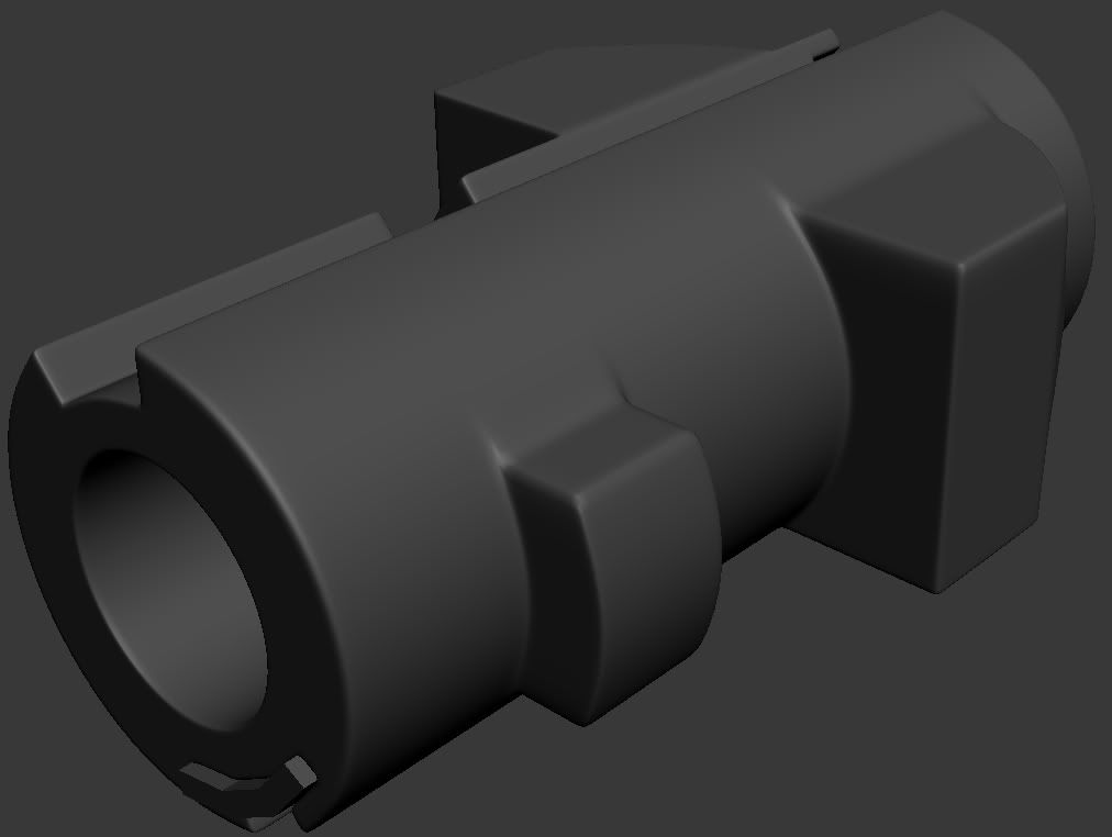
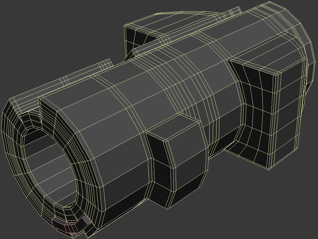
Thanks
Thanks
Replies
I was thinking of something like this, so the loops don't carry down the length of the cylinder, I'm sure there are other ways to deal with it.
EDIT: Ha Per beat me to it. He is WAY more experienced with this stuff so go with whatever he says =P
"Use trial and error, plus logic, to come up with a reasonable amount of geometry. Moar"
But yeah, in this case I would just do one of Per's examples really, the shape is mostly done, you don't have an absurdly low amount of segments, and any minor artifacts won't show in the end product.
The only problem with this method is that things can become relatively polygon heavy. (not really an issue IMO)
Also creates artifacts. Just use this rule :
"Use trial and error, plus logic, to come up with a reasonable amount of geometry. Moar"
Test stuff. Just do things to learn. It's cg... you can create and delete, create and delete and so on.
The main problem with this is you're removing control loops from the equation, which on the surface may seem like a good idea, but in reality you take away the easy, direct control of your edge widths.
Its fine for less-important stuff, but I wouldn't want to rely on it if you want real specific edge widths, as then you're relying on your overall topology instead of your control loops, which is a real big pain to redo if you don't like the end result, whereas you can simply slide your control loops around with the traditional method.
Also, like using edge weights, this falls into the realm of App specific workflow that doesn't translate/export well outside of max.
My TA working in Maya next to me just told me it's possible in Maya as well (not a specialist here, I can ask for more info if you are interested
Whats the point then if you have to add control loops as well?
Yeah, you can probably do something similar in Maya, but throwing it back and forth is a different issue(need to have reliable custom normals importing/exporting, which has always been a pain for me, maybe FBX can do a decent job these days?). And you're only talking Maya as well, there are other 3d apps in the world than Max and Maya.
Look, i'm not trying to tell you your method is useless, its just not a "silver bullet" that solves all things sub-d. There are specific drawbacks to it just like any workflow. It ends up with a lot more geo as you mention, you need to alter the way you model entirely, more evenly spaced geo like you would for sculpting meshes to control your edges, so you're just shifting where you put the work, and it may not transfer to other apps as well as traditional sub-d. For really simple shapes it can save a lot of time, for more complex stuff less so.
Most of the images posted so far still feature minor amounts of stretching at the corners of the extruded rectangle.
Perna's first image where he's got the 64 sided cylinder does the best job (by far) Which pretty much wrecks the whole "more geo is not a good rule" thing that is going on in this thread, because the best picture has the most geo..
I understand what you guys are going at, and at times its true that some rules that are meant as general guidelines are interpreted as words straight from the almighty CG god, but It's still true that the more geometry you have, the less stretching you get (with any method).
Of course there are times when massive amounts of geo is hard to work with in which cases it would totally be worth sacrificing perfection in order to have a topology that is workable.
From what I understand there is ALWAYS a bit of stretching. Even if you use 64 sided cylinder you get stretching but proportions of the stretch to the rest of the geometry makes it almost not visible.
Sew said the technique with smoothing groups doesn't add any stretching. It does. More geometry you have better shape will be preserved. More geometry = less control over mesh. Everything can be modelled but you need to have enough experience to be able to know how much geometry should be used.
Just use your brain and experiment. Perna showed many examples. 'MORE GEO' thread also has lots of meshes to look at. Take pernas guidelines and model! it needs to look good. It doesn't need to be atom perfect!
This is not the point of subdivision modeling. SubD is meant to be fast, easily editable, controlable, integrated in the whole low-poly/normal map workflow.
It comes with some imperfections that will barely be noticed anyway.
So, as usal in 3d, it's a matter of compromises.
more or less the same as: http://www.polycount.com/forum/showpost.php?p=1653908&postcount=10
That example would fall apart when baking, it will create a nightmare cage and won't capture seamlessly like per pointed out.
You can get around that by making your low poly one solid piece instead of separate pieces, but if you're going to do that you can take a few more seconds and figure out how to add enough control geometry to get the smoothing right. That will still be faster than having to create two separate objects for the high poly. Also the chances that you build your low poly with separate objects goes up when you build your high out of separate pieces. At that point you're probably thinking "I did this once I just need to make/remake it lower res" and you fall into a seam creating trap without realizing it.
I'm not saying never use floaters, but you have to know when they will cause problems and when its safe to use them. That normally means fully testing out these kinds of ideas and finding out why they worked or failed.
Lets say you figure out a cage that works with two separate low poly objects and it is now technically possible to get a good bake. Now you have to worry about the scale and distortion of the separate UV shells which will relax and distort differently if they aren't joined together. With them joined the normals of the cage match and whatever distortion is in the UV's, also matches.
Lets say you wanted to add some detail that runs down both pieces, like a panel break or weld marks, scratches dirt, dents or something else. With them as separate objects you have manage them both independently and try to get them to match, even if they do bake properly you still have the UV problems talked about above.
Seam city... that's why you have to fully test out the ideas to make sure they work, so great thinking but test it fully.
Virtually everything you say here is specific to how you construct the lowpoly, and has nothing to do with highpoly construction. If the floated object like sebas posted shows no seams in the viewport, it isn't going to show any seams in the bake.
If you split the lowpoly there as well, you'll get seams, but you'll get the same seams if you have a split lowpoly and a connected high, the issue you're bringing up is with the low. How you split up your lowpoly doesn't have anything to do with how your highpoly is split, your highpoly will generally be split into as many peices as makes sense to do, where your lowpoly should be split into the minimum amount to avoid seams and aliasing.
I do floaters like sebas showed here, and again, if it looks seamless in the viewport, there are no issues or drawbacks as far as the end result visual look. I won't argue with the worfklow issues, as I agree on a complicated asset it may be even more work to do this, but again, I do this pretty often with no issues. Its a nice way to seamlessly connect two complex objects with greatly varying topology.
In addition to that, any minor seams you'll see from the "floated lip" that show up zooming in way to far in your 3d app will most likely not be visible in the final bake. So those worries are overblown as well.
Real world example:
A. Messy floater thing
B. Oh no, I zoomed in too far at the worst possible angle, horrible seams!
C. Real world end result. No issues.
Edit: This is also a good argument for simply running a test bake and seeing what looks good at the intended texture resolution, instead of zooming in and getting all anal about minor artifacts shown in any of the various methods suggest in this thread. At the end of the day the only thing that matters is what shows up in the final bake, and it most cases you won't have the texture resolution for these little artifacts to show up, then you throw actual materials on top of it, texture compress, view it in game at 1/16th the size you're inspecting it at in your 3d app, and it all becomes very trivial.
The problem I think this example would run into is that its a floater on a round cylinder and the angle of the cage normal might pick up the lip because the lip might not be exactly perpendicular to the surface, like a floater on a flat surface would. But then like you said a quick test bake would let you know if you can move forward.
I still think you can run into problems if you want to add some high poly geometry detail that runs across the floater and the main mesh, managing them independently can be a pain in the ass, where if they are joined it can be done a lot easier and for big simple shapes like this its probably going to be easier to just have joined shapes.
I guess in those cases you can try to attach the floater and work out the edge flow then add the detail. But then you're doing more work to do what you should have done in the first place and you are probably introducing slop by trying to reconcile the two pieces.
I guess what I'm trying to say, is that it's very important to realize those sort of artifacts are only acceptable in some cases. If I saw something like a car body with those pinches, I wouldn't call it a good model.
I mostly use floaters on flat geometry where I know the lip will be parallel to the surface.
On one side Per is saying a pinch might not be renderable, and on the other side EQ is saying a lip seam might not be renderable. I'm sure they are both valid ways of working but I would be more nervous that the curved floater would mess up or be harder to work with. Still I can see myself using it on occasion...
Maybe this would help?
http://www.scriptspot.com/3ds-max/scripts/geometry-projection
I just remembered seeing this script a few weeks back, which might be really helpful in situations like this. I only tested it out on simple objects but it worked pretty well. More than likely it won't try to match the geometry so sub-divided results will probably be really ugly which might lead to seams? Totally need to test it out more.
It would be great if I could have this active in realtime on an instance so I could work on the straight version and the deformed version would update, but its a one shot deal. Still might be helpful when you need a floater to conform.
I like the idea of being able to work out the floater mesh independently of the main mesh and I guess I could merge them together if need be. This script would at least help get the surfaces parallel, but its up to you to figure out the connecting geometry (if you need to go that far, for some reason and I can think of a few).
I think you're overthinking it a little. If it looks good in the viewport, its going to bake fine. If its obviously messed up in the viewport the bake will be messed up too. The projection angle doesn't change the angle of the mesh itself, so it just has to be flush(or nearly flush within a certain tolerance, generally below the margin of error for the texture resolution).
Yes, this is a very valid point, if you need to carry detail between the two parts its a very bad method. I would only use it for very simple intersections.
Except i do, you probably haven't noticed because... Its not noticeable when I do it. =P I'm not doing it every day on every mesh or anything though, mostly just a case of being too lazy to merge it together(because the bake will be the same regardless).
Its a quick way to do a soft intersection without having to actually merge the meshes, sometimes its more work, sometimes its less, usually both provide the same quality. When its less work I do it, when its more work I don't.
Though you're right in the sense that I wouldn't do it in the exact case shown here. I do use it on larger forms though, not just small floaters. The funny thing here being you were the one who showed me how to do this many odd years ago.
Generally why I do it, sometimes I just don't bother connecting it, never really an issue(like I showed in the earlier example, I could have connected but it would have been more work for no/little gain).
Again, my main point is that it is a perfectly valid method if it gives you some workflow improvement or something. Quicker or faster to do? Do it, it can be in some situations. Of course it isn't the end-all-be-all for doing intersections, but who cares, it works.
Ok, same method but different test case. Nice for doing quick stuff like this. Sure you can take the time to merge it all in too, but its more time spent with no gain, and leaving it disconnected gives you a little bit of freedom to tweak the cylinder on one axis without messing with the base mesh. If your base mesh is more complex maybe merging it in is a significant pain. Maybe you want to leave it loose incase you get some change request, after you've merged stuff in like this it can be a lot of work to remodel it.
Its also a really nice way to drop complexity on a cylinder, say you have a 128 sided cylinder to do some ridges, but the cylinder extends past and you only want 24 sides on the rest, but don't want a visible seam. Just use a little floating lip and you've got a seamless mesh with two chunks.
PS: Mark, that script looks great for doing this sort of stuff, matching the surface area is generally the hard part.
Generating the low would be another point of concern, you still need to figure out how to merge those shapes to get the low poly to bake right, which people might not do with large shapes.
As long as people understand the problem of having separate pieces on the low poly and that it will create seams, I don't think it matters too much. Like everyone is saying "do what makes the most sense for what you are working on".
I might start floating more big shapes because of this thread where in the past I would mostly stick to small planar details.
Which actually brings up another idea... lets say you did need some high poly detail to go between the pieces, you might be able to sweep a shape over a spline that conforms to the surface.
Paint a spline over both shapes (or cut a line and convert to shape)
Sweep or pathdeform the shape over the spline and you have some details going over it.
I would knock the example together but hopefully you guys get the point, its roughly the same idea as this.
I do this sometimes with plate details where I don't want to make a mess of the larger shape just for some simple details, I kind of consider this lazy but fuck it there are times it just doesn't matter.
Threads like this are cool for discussion, but they'll get buried eventually, or the pics will die.